An optical cable identification device

A technology for identifying devices and optical cables, which is used in measuring devices, optical instrument testing, and testing of machine/structural components. , the effect of reducing the error rate and improving the accuracy

Inactive Publication Date: 2019-11-15
安徽电信器材贸易工业有限责任公司
View PDF7 Cites 0 Cited by
  • Summary
  • Abstract
  • Description
  • Claims
  • Application Information

AI Technical Summary

Problems solved by technology

[0003] The purpose of the present invention is to solve the problem that the position of the optical cable identification device in the prior art cannot be moved, and it is not easy to disassemble, maintain and replace, and propose an optical cable identification device

Method used


Image

  • An optical cable identification device
  • An optical cable identification device
  • An optical cable identification device

Examples


Embodiment Construction

[0014] The following will clearly and completely describe the technical solutions in the embodiments of the present invention with reference to the accompanying drawings in the embodiments of the present invention. Obviously, the described embodiments are only some, not all, embodiments of the present invention.

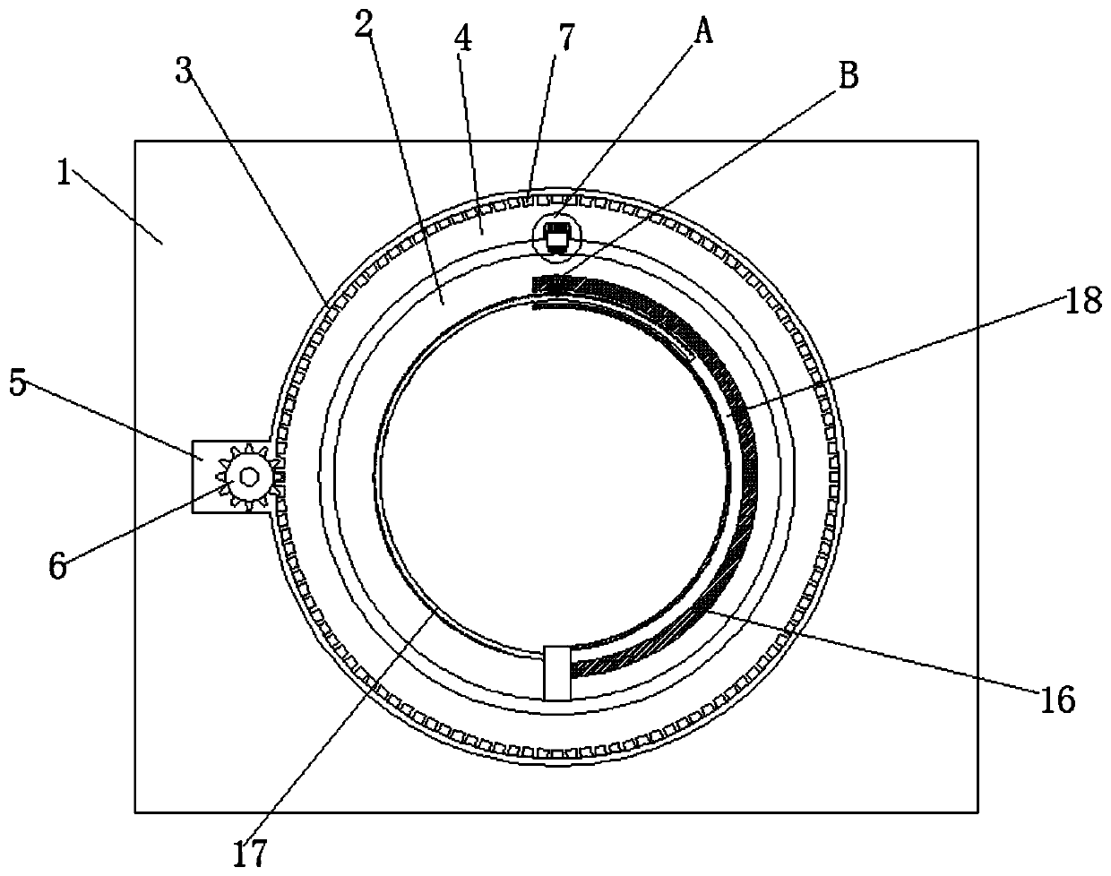
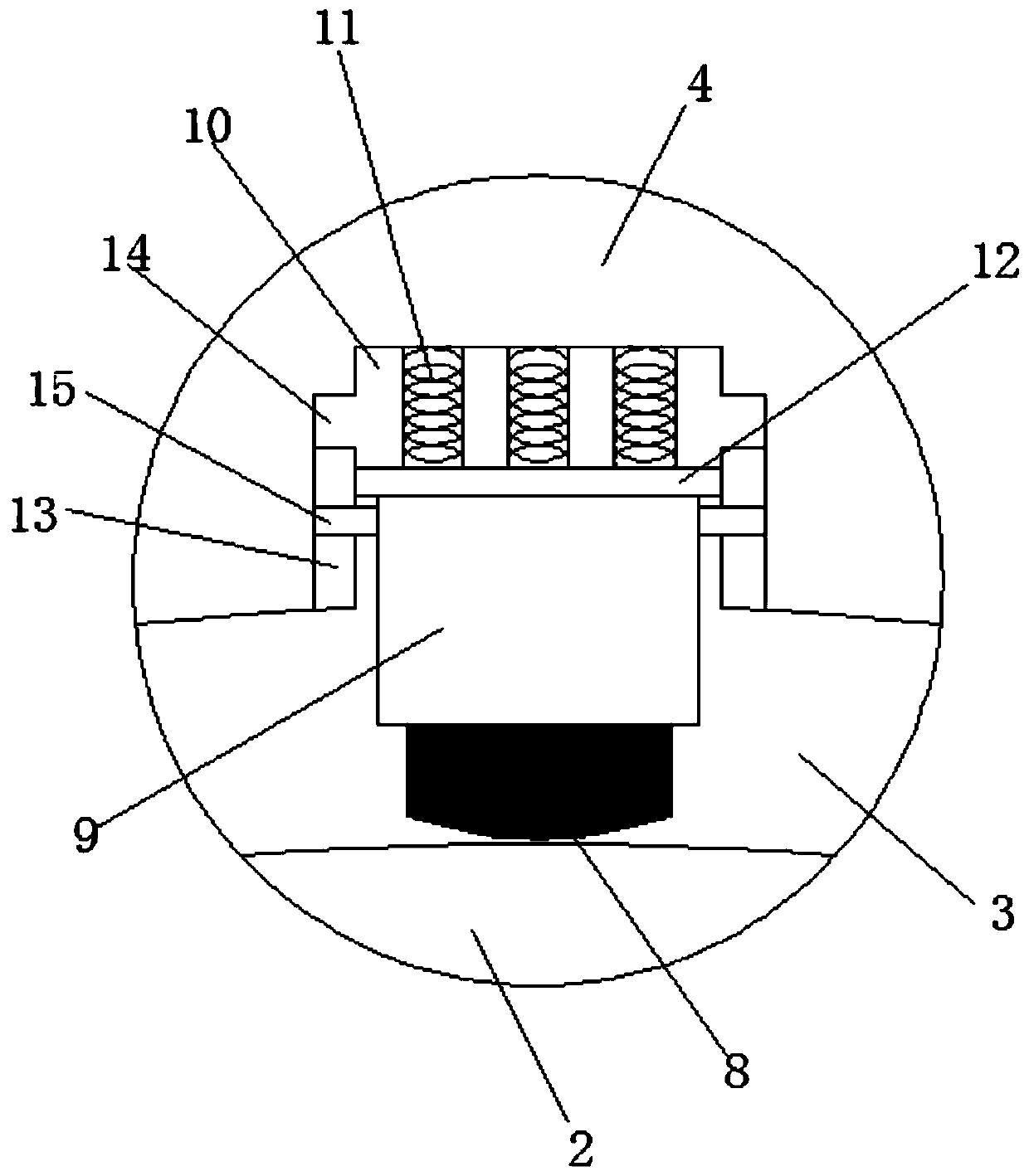
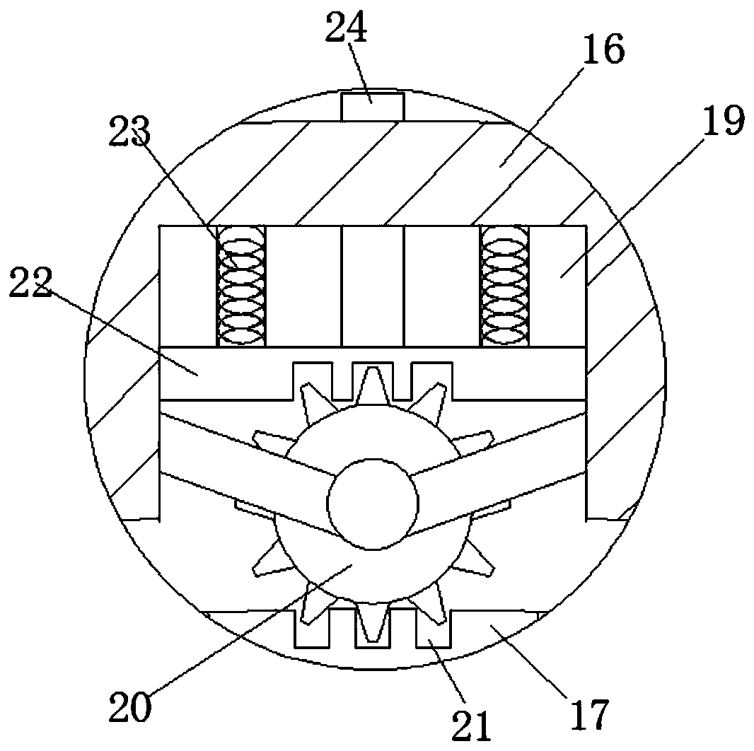
[0015] refer to Figure 1-3 , an optical cable identification device, comprising a housing 1, an identification chamber 2 is provided in the housing 1, and an annular rotating groove 3 is provided on the inner wall of the identifying chamber 2, and an annular rotating block matching it is rotatably connected to the annular rotating groove 3 4, and the inner wall of the annular turning block 4 is provided with an identification device 8, and the housing 1 is also provided with a groove 5 communicating with the annular turning groove 3, and a driving motor is arranged in the groove 5, and the output shaft of the driving motor is connected with a The first gear 6, and t...


PUM


Abstract

The invention discloses an optical fiber identification device, which comprises a shell body, wherein an identification cavity is formed in the shell body, an annular rotating groove is formed in theinner wall of the identification cavity, an annular rotating block matched with the annular rotating groove is rotatably connected in the annular rotating groove, the inner wall of the annular rotating block is provided with an identification device, and a groove communicated with the annular rotating groove is further formed in the shell body, a driving motor is arranged in the groove, an outputshaft of the driving motor is connected with a first gear, a plurality of first tooth grooves matched with the first gear are formed in the side wall of the annular rotating block in a surrounding manner, the identification device is connected with a mounting block, and a first mounting slot matched with the mounting block is formed in the annular rotating block. The optical fiber identification device facilitates the position rotation of the identification device, so that the identification device can perform identification operation on a plurality of parts of an optical cable conveniently, thereby improving the precision of identification; meanwhile, the optical fiber identification device facilitates the disassembly, replacement and overhauling of the identification device, thereby reducing an error rate of identification.

Description

technical field [0001] The invention relates to the technical field of optical cable maintenance, in particular to an optical cable identification device. Background technique [0002] The optical cable is the core unit in the optical fiber communication system. In practical applications, multiple optical cables are usually laid together. When maintaining and overhauling the optical cable, it is necessary to find the target optical cable from among the numerous optical cables, which brings great trouble to the maintenance personnel. . Therefore, how to quickly find the target optical cable from numerous optical cables has become a difficult problem encountered in the maintenance of the current optical fiber communication system; The identification operation leads to limitations in the identification process; at the same time, the identification device is prone to errors after long-term use, and it is inconvenient to disassemble for maintenance; therefore, we propose an opti...

Claims


Application Information

Patent Timeline
Patent Type & Authority Patents(China)
IPC IPC(8): G01M11/00
CPCG01M11/00
Inventor 陈铁牛张坤黄晓玲
Owner 安徽电信器材贸易工业有限责任公司
Why Eureka
Try Eureka