Blanking, stretching and punching die

A blanking die and punch punch technology, which is applied to forming tools, manufacturing tools, feeding devices, etc., can solve the problem of affecting the service life of the fan coil in the hemming process, punching cracks, uneven force on the punching edge, etc. problem, to achieve the effect of short punching action time, reducing the generation of punching cracks, and less cracks

Active Publication Date: 2018-05-22
ZHEDIAN METAL TECH SHANGHAI
View PDF5 Cites 5 Cited by
  • Summary
  • Abstract
  • Description
  • Claims
  • Application Information

AI Technical Summary

Problems solved by technology

In the prior art, when punching, because the force on the edge of the punching is often uneven, the edge of the

Method used


Image

  • Blanking, stretching and punching die
  • Blanking, stretching and punching die
  • Blanking, stretching and punching die

Examples


Embodiment Construction

[0054] The present invention will be further described in detail below with reference to the examples and figures, but the embodiments of the present invention are not limited thereto.

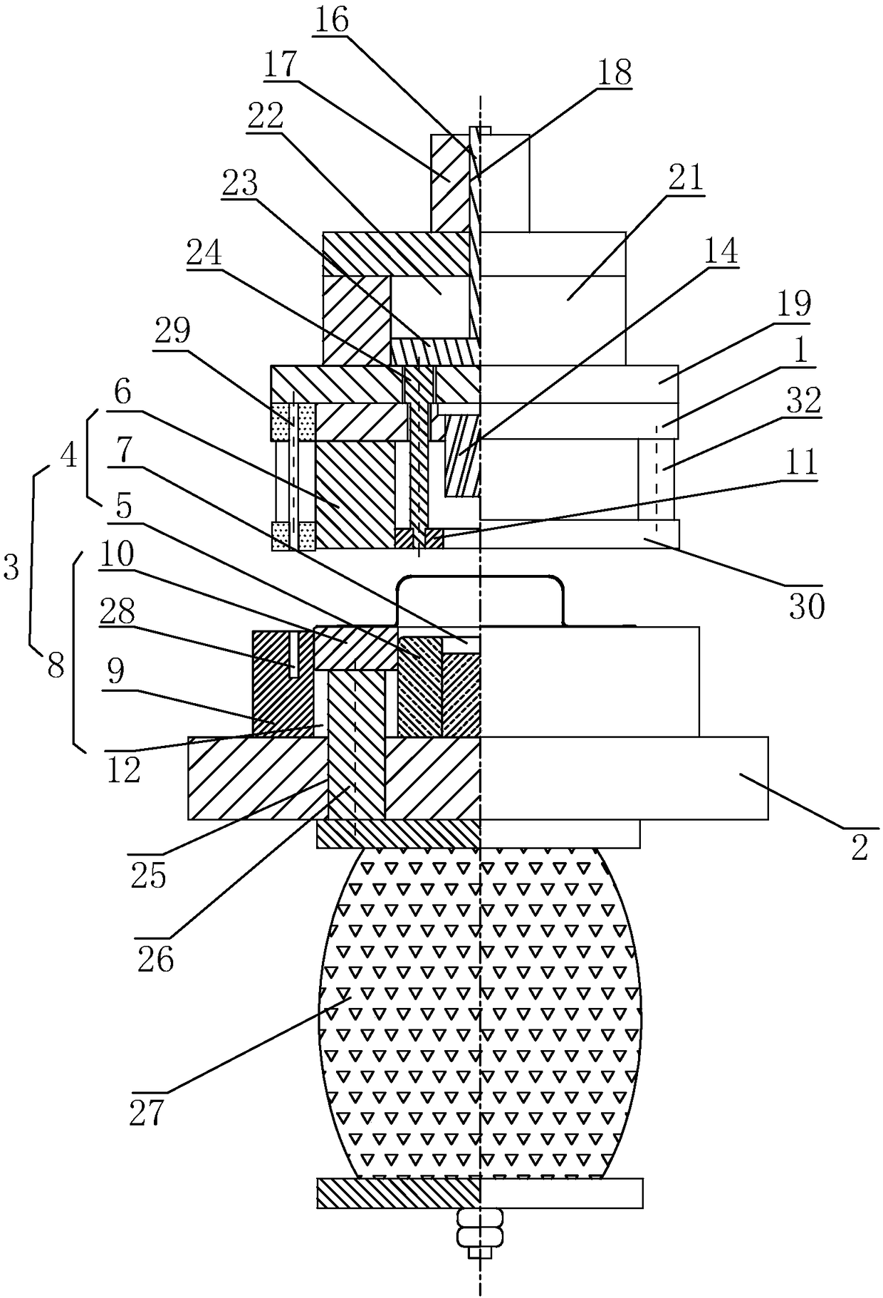
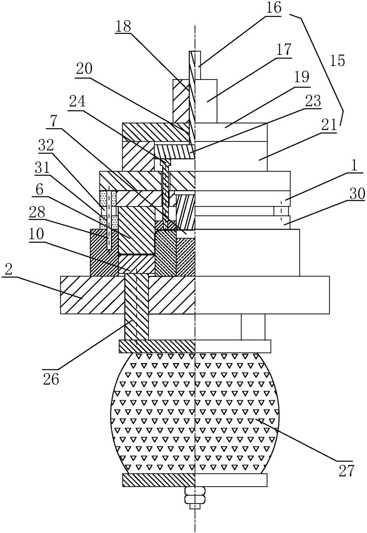
[0055] A blanking stretch punching die, combined with figure 1 with figure 2 As shown, it mainly includes an upper template 1, a lower template 2 and a stretch punching assembly 3.

[0056] Wherein, the stretch punching assembly 3 includes: a stretching die set 4, a pressing die set 8, a punching die set, and a driving part.

[0057] The driving member includes a driving device and a transmission module 15 arranged between the driving device and the upper template 1 . The driving device drives the transmission module 15 to push the upper template 1 to move up and down.

[0058] The stretching die set 4 includes a stretching punch 5 fixedly connected to the upper end surface of the lower template 2 and a stretching die 6 fixedly connected to the upper template 1 . The stretching punch 5 is...


PUM


Abstract

The invention discloses a blanking, stretching and punching die. The blanking, stretching and punching die comprises an upper die plate, a lower die plate and a stretching and punching assembly. The stretching and punching assembly comprises a stretching module, a material pressing module, a punching module and a driving component. The material pressing module comprises a blanking female die, a material pressing plate and a material pushing plate. By means of the material pressing plate, a stretching female die and the material pushing plate, when a panel is punched through a punching male die, the panel is fixed thoroughly and prevented from moving in the same direction as the punching male die when being impacted; mechanical kinetic energy of the punching male die is made to act on punching in a more-concentrative manner; and punching cracks are reduced. A containing groove is formed in the upper die plate and internally provided with an elastic energy storage part, and therefore, after the end of the punching male die makes contact with a to-be-punched part, energy storage is started; and then, the stored mechanical kinetic energy is released within a short time, the punching action time of the punching male die is shorter, and a smaller number of cracks are generated at the edge of a punched hole.

Description

technical field [0001] The invention relates to the technical field of forming dies, more specifically, it relates to a blanking, stretching and punching die. Background technique [0002] With the development of industry, the application of stamping dies is becoming more and more extensive. At the same time, due to the acceleration of product replacement, in addition to ensuring the quality of mold design, the requirements for the practicability and applicability of molds are also getting higher and higher. [0003] At present, in the process of producing fan coils, the process of stretching and punching is mostly used. In the prior art, when punching, the force on the edge of the punching hole is often uneven, resulting in the phenomenon of cracking on the edge of the punching hole, which affects the subsequent curling process and the service life of the entire fan coil. In order to solve the above problems, the Chinese patent with the patent announcement number CN205763...

Claims


Application Information

Patent Timeline
IPC IPC(8): B21D37/08B21D35/00B21D43/00B21D28/26B21D19/00B21D37/04
CPCB21D19/005B21D28/26B21D35/001B21D37/04B21D37/08B21D43/003
Inventor 王斌张平张怿林胡久亮
Owner ZHEDIAN METAL TECH SHANGHAI
Why Eureka
Try Eureka