Main support beam fatigue test device

A technology for fatigue testing and supporting beams, which is applied in measuring devices, testing of mechanical components, testing of machine/structural components, etc., can solve problems such as fatigue of main supporting beams, and achieve the effect of easy disassembly and simple structure

Active Publication Date: 2018-06-15
CHINA HELICOPTER RES & DEV INST
View PDF4 Cites 2 Cited by
  • Summary
  • Abstract
  • Description
  • Claims
  • Application Information

AI Technical Summary

Problems solved by technology

[0003] The purpose of the present invention is to provide a fatigue test device for the main reduction

Method used


Image

  • Main support beam fatigue test device
  • Main support beam fatigue test device
  • Main support beam fatigue test device

Examples


Embodiment Construction

[0021] In order to make the objectives, technical solutions and advantages of the present invention clearer, the technical solutions in the embodiments of the present invention will be described in more detail below in conjunction with the drawings in the embodiments of the present invention. In the drawings, the same or similar reference numerals denote the same or similar elements or elements having the same or similar functions throughout. The described embodiments are some, but not all, embodiments of the invention. The embodiments described below by referring to the figures are exemplary and are intended to explain the present invention and should not be construed as limiting the present invention. Based on the embodiments of the present invention, all other embodiments obtained by persons of ordinary skill in the art without creative efforts fall within the protection scope of the present invention. Embodiments of the present invention will be described in detail below ...


PUM


Abstract

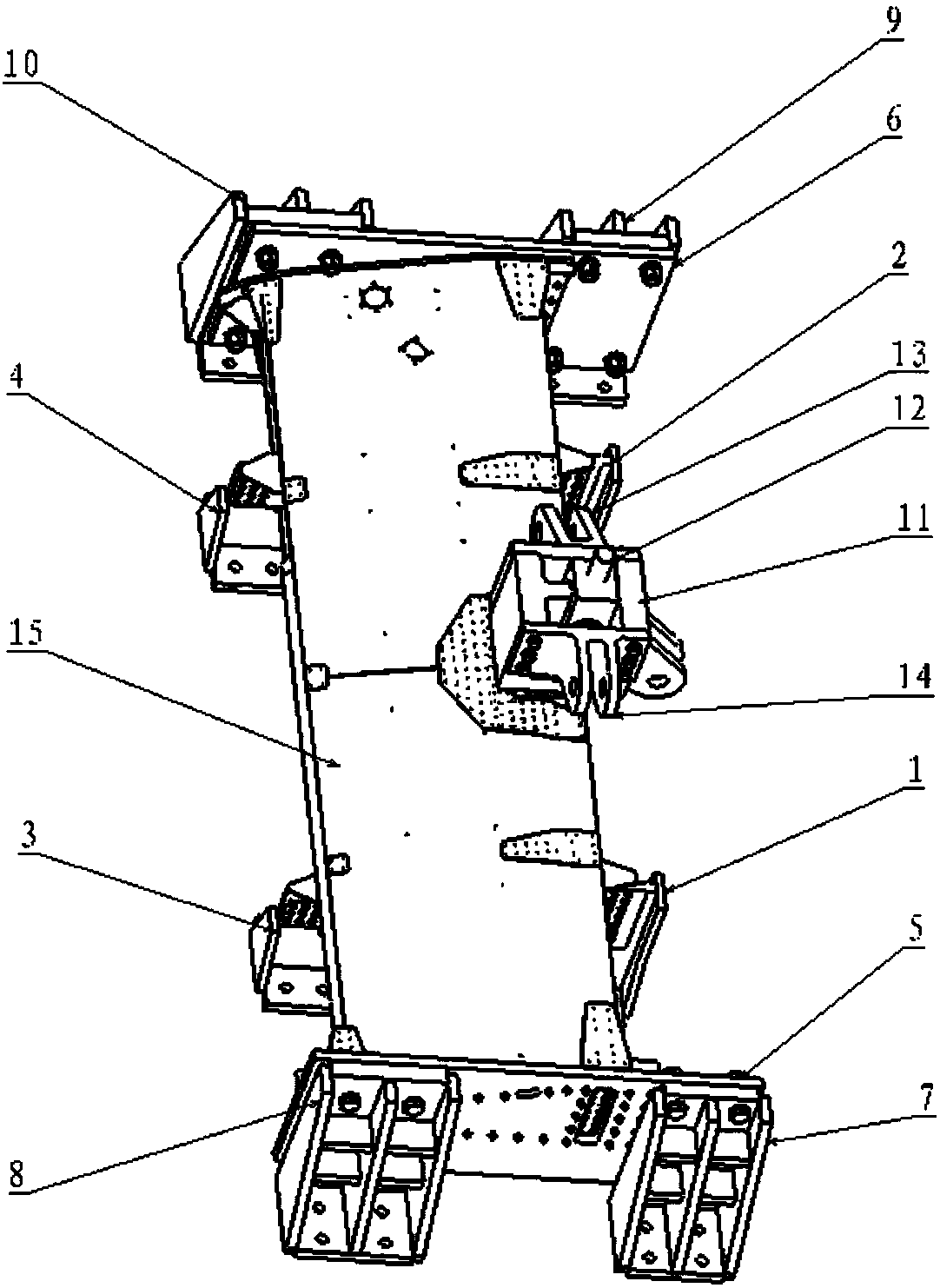
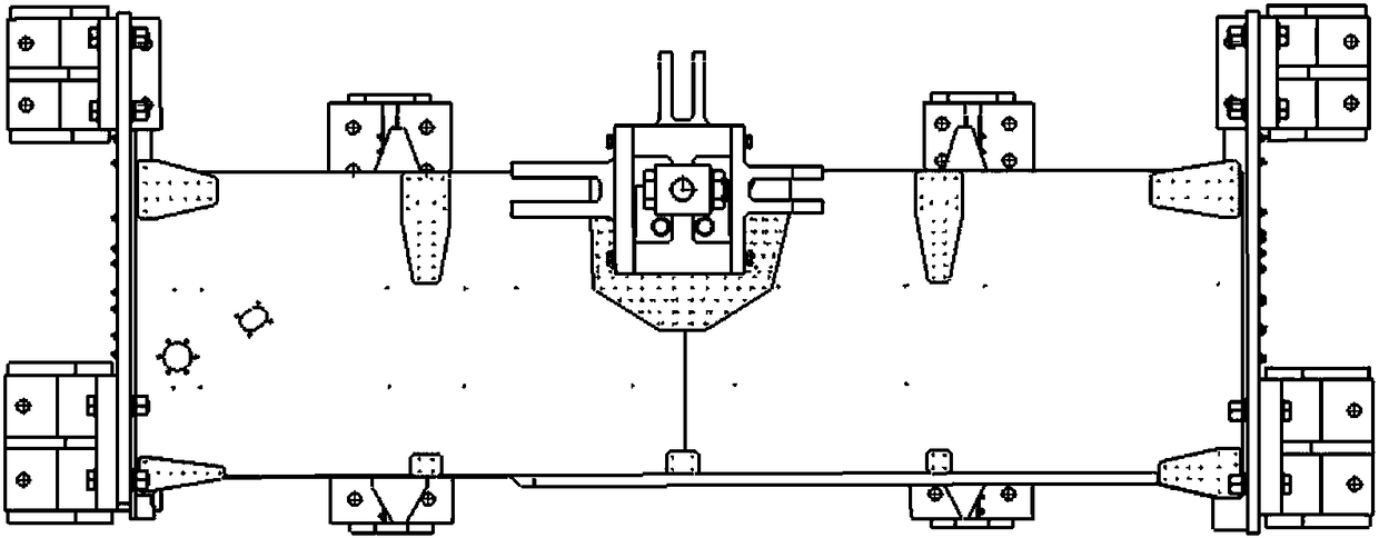
The present invention relates to the technical field of helicopter main support beam tests, especially to a main support beam fatigue test device. The device comprises a main support beam (15), connection support seats and a load module. There are four connection support seats arranged on the main support beam (15); the load module comprises an X-directional load loading joint (11), a Z-directional load connection fork ear (12), a Y-directional balance load loading joint (13) and a Y-directional load loading joint (14), wherein the X-directional load loading joint (11), the Z-directional loadconnection fork ear (12) and the Y-directional load loading joint (14) are configured to apply loads in X, Y and Z directions to a main support beam fatigue test device, and the Y-directional balanceload loading joint (13) is configured to eliminate the bending moment of a Y-directional load to a connecting bolt. The main support beam fatigue test device is simple in structure and convenient to dismount, can meet boundary simulation when the main support beam fatigue test is performed, and can apply load to the main support beam according to test requirements.

Description

technical field [0001] The invention relates to the technical field of helicopter main reduction support beam tests, in particular to a fatigue test device for main reduction support beams. Background technique [0002] The main reduction support beam is an important load-bearing part of the helicopter. In order to grasp the fatigue life of the main reduction support beam, the fatigue test must be carried out on the main reduction support beam, and the fatigue characteristics of the main reduction support beam are obtained, and then the life of the main reduction support beam is given. The main reducing support beam needs to apply loads in the X, Y, and Z directions to the test piece at the same time during the test. At the same time, when the Y direction is applied, the bending moment of the Y direction load on the connecting bolts must be eliminated. Therefore, a Y direction must be applied in the Y direction. Balance the load towards the bending moment. At present, there...

Claims


Application Information

Patent Timeline
IPC IPC(8): G01M13/00G01N3/08
CPCG01M13/00G01N3/08
Inventor 夏国旺王智景胡景燕
Owner CHINA HELICOPTER RES & DEV INST
Why Eureka
Try Eureka