Spiral steel pipe shape adjusting auxiliary system and auxiliary shape adjusting method

A technology of spiral steel pipes and auxiliary systems, applied in auxiliary devices, auxiliary welding equipment, welding/cutting auxiliary equipment, etc., can solve problems such as misalignment and seam opening, eliminate positive and negative misalignment, improve geometric contour accuracy, reduce The effect of waste reduction

Active Publication Date: 2018-06-22
BC P INC CHINA NAT PETROLEUM CORP +2
View PDF11 Cites 5 Cited by
  • Summary
  • Abstract
  • Description
  • Claims
  • Application Information

AI Technical Summary

Problems solved by technology

[0004] The purpose of the present invention is to provide a spiral steel pipe adjustment auxiliary system and auxiliary adjustment method, aiming to solve the technical problems of the head end of the tube blank and the spiral seam near the meshing center of the tube blank spiral seam.

Method used


Image

  • Spiral steel pipe shape adjusting auxiliary system and auxiliary shape adjusting method
  • Spiral steel pipe shape adjusting auxiliary system and auxiliary shape adjusting method
  • Spiral steel pipe shape adjusting auxiliary system and auxiliary shape adjusting method

Examples


Embodiment 1

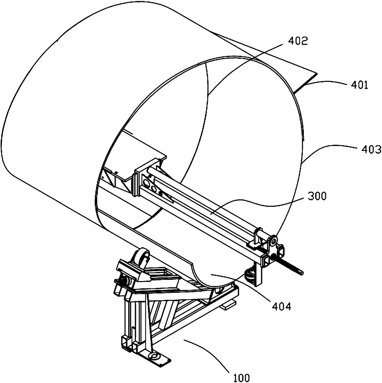
[0071] see figure 1 , the spiral steel pipe adjustment auxiliary system provided by the present invention will now be described.

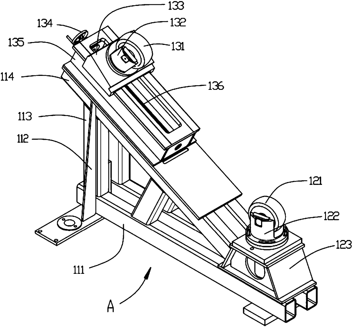
[0072] The auxiliary system for adjusting the shape of the spiral steel pipe includes an outer support device 100 arranged under the head 404 of the pipe blank and a seam joint roller device 300 arranged at the head end 403 of the pipe blank. The tube blank external support device 100 includes a base and more than two outer support roller mechanisms arranged on the base, the support point of the outer support roller mechanism is attached to the outer wall of the tube blank head 404 for Supporting the pipe blank matches the design pipe diameter of the spiral steel pipe to be processed. The seaming roller device 300 includes a hanger 310, a seam roller mechanism 320 slidingly limited on the hanger 310, and drives the seam roller mechanism 320 to engage with the spiral seam of the tube blank on the hanger 310 The seaming roller translation mechanism...

Embodiment 2

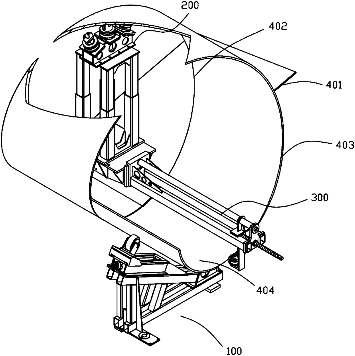
[0092] see figure 2 , in this embodiment, the spiral steel pipe shape adjustment auxiliary system includes the pipe blank outer support device 100 arranged under the pipe blank head 404, the pipe blank seaming roller device 300 that limits the pipe blank head end 403, and supports the pipe blank The inner supporting device 200 of the tube blank of the top wall. The tube blank outer support device 100 includes a base and more than two outer support roller mechanisms arranged on the base, the support point of the outer support roller mechanism is attached to the outer wall of the tube blank head 404, and is used to support the tube blank. The tube blank matches the design diameter of the spiral steel pipe to be processed. The seam joint roller device 300 includes a hanger 310 , a seam joint roller mechanism 320 slidingly limited on the hanger 310 , and drives the joint seam roller mechanism 320 to spiral toward the tube blank on the hanger 310 . The seam meshing roller transl...


PUM


Abstract

The invention discloses a spiral steel pipe shape adjusting auxiliary system and a shape adjusting method. The spiral steel pipe shape adjusting auxiliary system comprises a pipe blank outer support device arranged below a pipe blank head, and a joint closing roller device at a limiting pipe blank head end. The pipe blank outer support device comprises a base and two or more outer support roller mechanisms arranged on the base. Support points of the outer support roller mechanisms are attached to the outer wall of the pipe blank head and are used for supporting a pipe blank to be matched withthe designed pipe diameter of a plan-machined spiral steel pipe. The joint closing roller device comprises a hanging seat, a joint closing roller mechanism slidably limited on the hanging seat, and ajoint closing roller translation mechanism driving the joint closing roller mechanism to achieve translation on the hanging seat towards the meshing center direction of a pipe blank spiral joint. Thejoint closing roller mechanism is provided with a limiting annular groove limiting the limiting pipe blank head end. With adoption of the spiral steel pipe shape adjusting auxiliary system, the technical problems of the low head of the pipe blank head end of the spiral steel pipe and spiral joint misalignment and joint opening near the meshing center of the pipe blank spiral joint are solved.

Description

technical field [0001] The invention belongs to the technical field of large-diameter spiral steel pipe processing, and more specifically relates to a spiral steel pipe adjustment auxiliary system and an auxiliary adjustment method. Background technique [0002] In recent years, the diameter and specifications of water delivery steel pipes demanded by the market have gradually increased. When the traditional three-roller bending plate spiral forming method with external control rollers is used to produce steel pipes with large diameters (above Φ2032) of ordinary materials, it is difficult to adjust the shape of the steel pipes; Especially when the diameter-to-thickness ratio of the steel pipe is ≥120, due to the generally low yield strength of the base metal, the delivery edge of the steel strip and the free edge of the billet during the shape adjustment process of the pipe billet are prone to positive and negative misalignment, the head end of the pipe billet bows, and the p...

Claims


Application Information

Patent Timeline
Patent Type & Authority Applications(China)
IPC IPC(8): B21D5/14B21D43/00B23K37/00
CPCB21D5/14B21D43/00B23K37/00
Inventor 王军田鹏王晓颖吴秀宇杨明秦闫立学邱玉亮
Owner BC P INC CHINA NAT PETROLEUM CORP
Why Eureka
Try Eureka