Structure and method for realizing high ground stress relief of deep ground based on phase change guided pre-cracking

A technology of high in-situ stress and stress-releasing holes, which is applied in earth-moving drilling, mining fluids, mining equipment, etc., can solve the problems of surrounding rock disturbance, increase drilling density, prolong construction period, etc. rockburst effect

Active Publication Date: 2018-06-22
XIAN UNIV OF SCI & TECH
View PDF6 Cites 1 Cited by
  • Summary
  • Abstract
  • Description
  • Claims
  • Application Information

AI Technical Summary

Problems solved by technology

The specific methods mainly include: (1) release pressure by pre-drilling holes in high stress areas; (2) release stress in high stress areas by weak blasting method; (3) release stress by spraying cold water in high stress areas. But the above There are still some obvious deficiencies in the three methods, which are as follows: (1) Although the problem of stress release can be solved by drilling, the stress release is relatively slow, which brings certain dangers to the staff, but the speed of stress release should be accelerated. , it is necessary to increase the density of drilling holes, prolong the construction period, increase the production cost and shorten the life of the drilling machine
(2) ① It is difficult to control the amount of charge and the effect of smooth blasting by using the drill and blast method, which in turn leads to disturbance of the surrounding rock
③The hole depth and blasting depth cannot be strictly controlled
But this may only have a significant effect on rock masses with low strength, but it is difficult to achieve the desired effect on rock masses with high strength and brittleness.

Method used


Image

  • Structure and method for realizing high ground stress relief of deep ground based on phase change guided pre-cracking
  • Structure and method for realizing high ground stress relief of deep ground based on phase change guided pre-cracking
  • Structure and method for realizing high ground stress relief of deep ground based on phase change guided pre-cracking

Examples


Embodiment Construction

[0031] The present invention will be described in further detail below in conjunction with specific examples, but the embodiments of the present invention are not limited thereto.

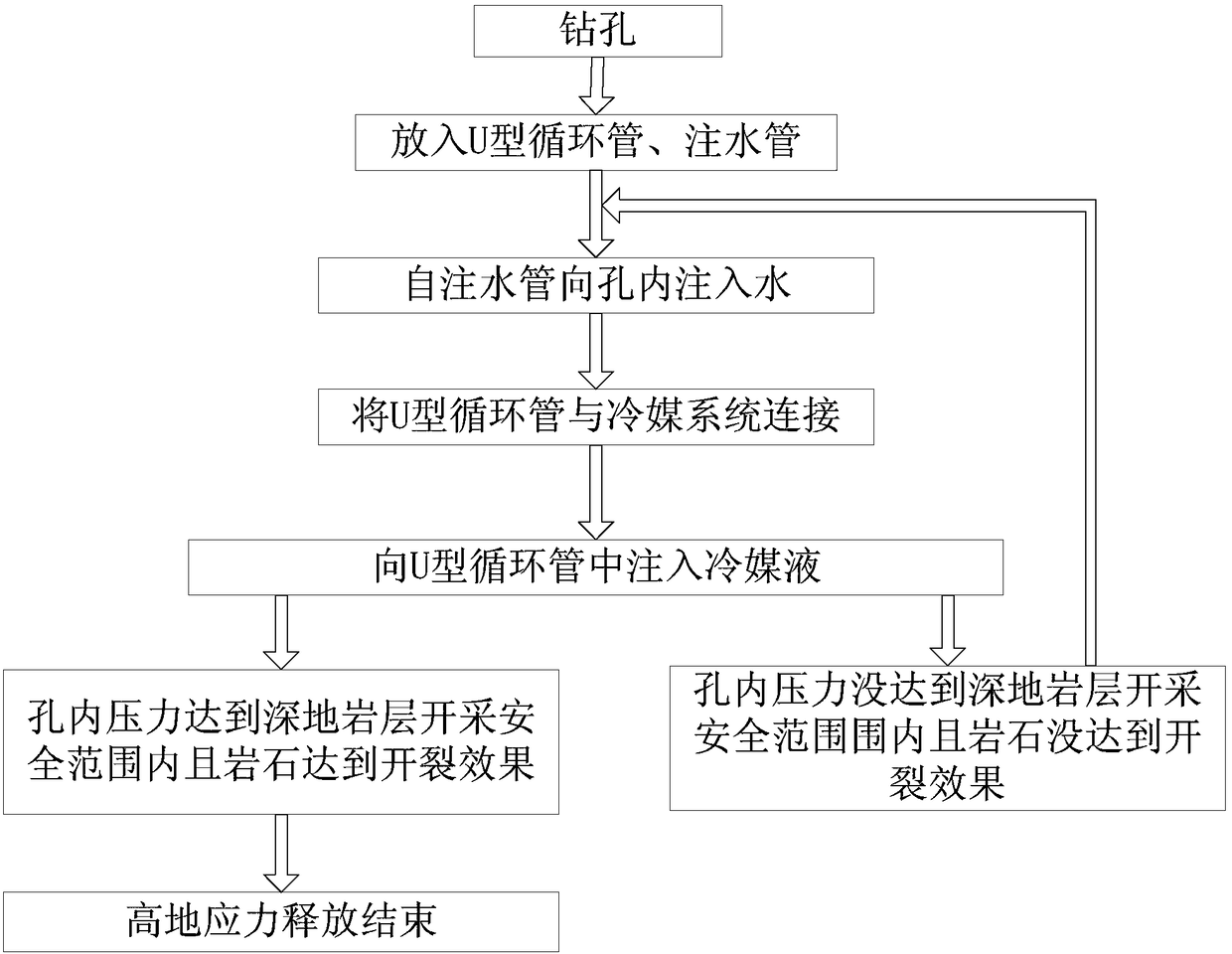
[0032] This embodiment provides a safe, efficient and fast method for releasing deep rock drilling prestress, including the following steps:

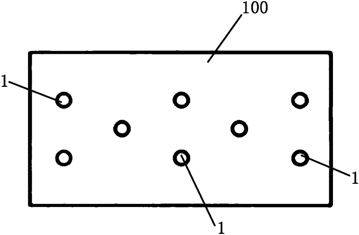
[0033] Step 1. Using a rock drilling rig to open a plurality of stress relief holes 1 in the rock formation 100, the plurality of stress relief holes 1 are arranged in five patterns or in the shape of a meter;

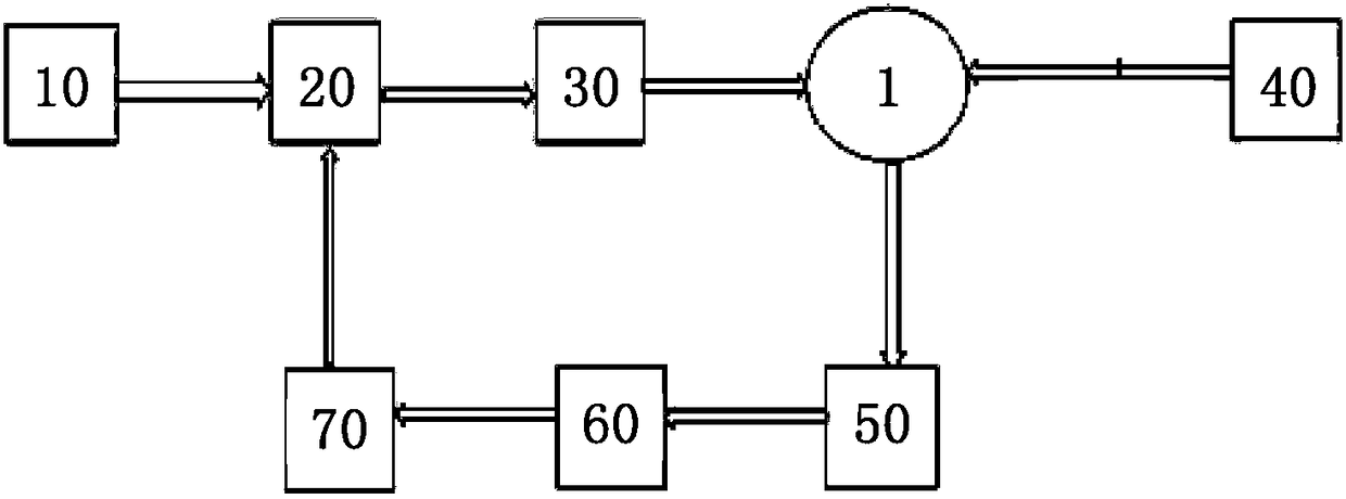
[0034] Step 2: On the surrounding wall of the induction ring 4, open a plurality of through holes for the sensor head to protrude from. The inner cavity of the induction ring 4 is equipped with a temperature sensor and a pressure sensor, and then the induction ring 4 is fixed on the U-shaped circulation pipe. 2, to realize the real-time collection of the temperature and pressure of the water in the stress relief hole 1; insert a U-shaped circulation ...


PUM


Abstract

The invention relates to a structure and a method for realizing high ground stress relief of deep ground based on phase change guided pre-cracking. The method comprises the steps that high-pressure water is firstly injected into a deep ground rock formation to complete first time high ground stress relief; refrigerant liquid conducts cold energy to the high-pressure water, the water reaches the phase change temperature, a crack of the rock formation further expands, and second time high ground stress relief is completed; circulation of the refrigerant liquid is stopped, and third time high ground stress relief is completed after ice is melted into water. According to the structure and the method for realizing the high ground stress relief of the deep ground based on the phase change guidedpre-cracking, a phase change principle is used to perform the high ground stress relief, thereby reducing the possibility of rock burst and increasing the rock drilling rate.

Description

technical field [0001] The invention belongs to a stress pre-releasing method in deep-earth energy development, and in particular relates to a structure and method for realizing deep-earth and high-earth stress release based on phase-change oriented pre-cracking. Background technique [0002] Deep ground is often characterized by high temperature and high pressure, among which rockburst is a typical phenomenon characterized by high ground stress. Rockburst phenomenon is common in deep rock drilling, which greatly affects the process of deep energy mining, and seriously threatens the safety of personnel and property in the process of deep mining. It has become an urgent technology to be solved in the process of deep energy development. question. For example, on August 15, 2016, a rockburst accident occurred in the deep development of Liangbaosi Coal Mine in Jining, Shandong Province, causing 2 casualties, and high compensation was paid to them; on March 9, 2014, Gongshan, Yu...

Claims


Application Information

Patent Timeline
Patent Type & Authority Applications(China)
IPC IPC(8): E21F17/00E21B43/26E21B43/20
CPCE21B43/20E21B43/26E21F17/00
Inventor 申艳军张欢侯新王永志
Owner XIAN UNIV OF SCI & TECH
Why Eureka
Try Eureka