Improved power supply plugging equipment

A power supply plug-in and improved technology, applied in the field of electric power, can solve the problems of unstable power supply connection, power failure of electrical equipment, electric shock accidents, etc., to prevent damage caused by sudden power failure, increase the safety of use, and ensure the safety and stability of power supply. Effect

Inactive Publication Date: 2018-06-29
杨明华
View PDF0 Cites 2 Cited by
  • Summary
  • Abstract
  • Description
  • Claims
  • Application Information

AI Technical Summary

Problems solved by technology

[0002] At present, the energization of electrical equipment is mainly to insert the plug connected to the electrical equipment into the power supply hole of the socket and clamp it tightly. Although this clamping method is simple to operate, the plug can still be pulled out directly after the plug is inserted into the power supply hole. When kicking by mistake hits the cable connected between the plug and the electrical equipment, it will cause the plug to be disengaged from the power supply hole, resulting in a sudden power failure of the electrical equipment. Therefore, the existing The clamping method has the risk of unstable power supply connection, which is likely to cause sudden power failure and damage to the electrical equipment. In addition, when the electrical equipment is not in use, its plug is often pulled out from the power supply hole, and the power supply hole is exposed. , if a child inserts the metal rod directly into the power supply hole while playing, it will cause an electric shock accident, so there is a big potential safety hazard

Method used


Image

  • Improved power supply plugging equipment
  • Improved power supply plugging equipment
  • Improved power supply plugging equipment

Examples


Embodiment Construction

[0019] The preferred embodiments of the present invention will be described in detail below in conjunction with the accompanying drawings, so that the advantages and features of the present invention can be more easily understood by those skilled in the art, so as to define the protection scope of the present invention more clearly.

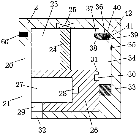
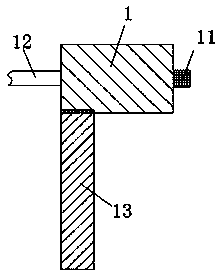
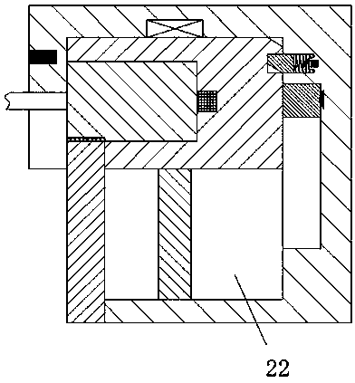
[0020] refer to Figure 1-4 An improved power supply plug-in device is shown, including a power connection part connected to the electric equipment and a power supply part connected to the mains, the power connection part is connected to the power consumption device through a cable 12, and the power connection part The components include a main body 1, a plug 11 is provided on the right end surface of the main body 1, a detachable limit baffle 13 is provided on the left side of the bottom end of the main body 1, the power supply part includes a base 2, the The bottom of the left end surface of the abutment 2 is provided with an inner concave open...


PUM


Abstract

The invention discloses improved power supply plugging equipment. The improved power supply plugging equipment comprises a power connection part connected with electric equipment and a power supply part connected with the mains supply, the power connection part is connected with the electric equipment through a cable and comprises a main body part, a plug is arranged in the right end face of the main body part, a detachable limiting baffle plate is arranged on the left side of the bottom end face of the main body part, the power connection part comprises a base station, an indent opening is arranged in the bottom part of the left end face of the base station, and a lower groove is arranged in the wall at the right end of the indent opening. The improved power supply plugging equipment is simple in structure, the power supplying stability is good, the main body part is safely and firmly locked, the operations of locking and unlocking the main body part are simple and convenient, a powersupplying hole is always at the power-off state when the main body part is inserted into or unplugged out of an installation groove, the electric shock accident caused when the main body part is inserted into or unplugged out of the installation groove is avoided, the life safety of people is guaranteed, and the whole device runs safely and reliably.

Description

technical field [0001] The invention relates to the field of electric power, in particular to an improved power supply plug-in device. Background technique [0002] At present, the energization of electrical equipment is mainly to insert the plug connected to the electrical equipment into the power supply hole of the socket and clamp it tightly. Although this clamping method is simple to operate, the plug can still be pulled out directly after the plug is inserted into the power supply hole. When kicking by mistake hits the cable connected between the plug and the electrical equipment, it will cause the plug to be disengaged from the power supply hole, resulting in a sudden power failure of the electrical equipment. Therefore, the existing The clamping method has the risk of unstable power supply connection, which is likely to cause sudden power failure and damage to the electrical equipment. In addition, when the electrical equipment is not in use, its plug is often pulled ...

Claims


Application Information

Patent Timeline
Patent Type & Authority Applications(China)
IPC IPC(8): H01R13/639H01R13/70H01R13/717
CPCH01R13/639H01R13/701H01R13/717
Inventor 杨明华
Owner 杨明华
Why Eureka
Try Eureka