Improved power plugging power supply device

A power supply device and an improved technology, which is applied to the parts of the connection device, coupling devices, circuits, etc., can solve the problems of large force applied by the plug, unstable power supply connection, damage to electrical equipment, etc., and achieve locking and unlocking operations Simple and convenient, the locking operation is simple and convenient, and the effect of ensuring life safety

Inactive Publication Date: 2018-07-03
舒丽燕
View PDF6 Cites 2 Cited by
  • Summary
  • Abstract
  • Description
  • Claims
  • Application Information

AI Technical Summary

Problems solved by technology

[0002] At present, the energization of electrical equipment is mainly to insert the plug connected to the electrical equipment into the power supply hole of the socket and clamp it to power on. Although this clamping method is simple to operate, the plug can still be used after the plug is inserted into the power supply hole. If it is pulled out directly, when it hits the cable connected between the plug and the electrical equipment by mistake, it will cause the plug to be disengaged from the power supply hole, resulting in a sudden power failure of the electrical equipment. Therefore, the existing This clamping method has the risk of unstable power supply connection, and it is easy to cause damage to the electrical equipment due to sudden power failure. Moreover, the existing clamping method requires a large force to be applied when the plug is pulled out, which is relatively difficult to pull out. strenuous

Method used


Image

  • Improved power plugging power supply device
  • Improved power plugging power supply device
  • Improved power plugging power supply device

Examples


Embodiment Construction

[0019] The preferred embodiments of the present invention will be described in detail below in conjunction with the accompanying drawings, so that the advantages and features of the present invention can be more easily understood by those skilled in the art, so as to define the protection scope of the present invention more clearly.

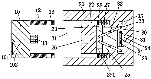
[0020] refer to Figure 1-4 The shown improved plug-in power supply device includes a power connection assembly connected to the electrical equipment and a power supply assembly arranged in the wall. The power connection assembly includes a push-pull block 10, and the push-pull block 10 Two inserting rods 12 are arranged symmetrically at the front and rear ends of the right end face, and a locking groove 13 is provided at each right end of the two inserting rods 12, and a plug 11 is arranged in the middle of the right end face of the push-pull block 10, so that The power supply assembly includes a base body 20, the left end of the base body 20 is...


PUM


Abstract

The invention discloses an improved power plugging power supply device comprising a power connection component which is connected with electricity utilization equipment and a power supply component which is arranged in the wall. The power connection component comprises a push-pull block. The front and rear ends of the right end surface of the push-pull block are symmetrically provided with two inserting rods. The right end of each of the two inserting rods is provided with a locking slot. The middle of the right end surface of the push-pull block is provided with a plug. The power supply component comprises a base body. The left end surface of the base body is provided with an accommodating slot which is used for being cooperatively connected with the push-pull block, wherein the opening of the accommodating slot is towards the left. The middle of the right end wall of the accommodating slot is provided with power supply jacks used for being cooperatively connected with the plug. The power plugging power supply device is simple in structure and great in power supply stability so that the electric shock accident can be avoided while the power connection component is unplugged and the life safety of people can be guaranteed; besides, the whole device operates safely and reliably, locking and unlocking operation of the inserting rod and the plug is easy and convenient, and unplugging of the power connection component is convenient and labor-saving.

Description

technical field [0001] The invention relates to the field of electric power supply, in particular to an improved electric plug-in power supply device. Background technique [0002] At present, the energization of electrical equipment is mainly to insert the plug connected to the electrical equipment into the power supply hole of the socket and clamp it to power on. Although this clamping method is simple to operate, the plug can still be used after the plug is inserted into the power supply hole. If it is pulled out directly, when it hits the cable connected between the plug and the electrical equipment by mistake, it will cause the plug to be disengaged from the power supply hole, resulting in a sudden power failure of the electrical equipment. Therefore, the existing This clamping method has the risk of unstable power supply connection, and it is easy to cause damage to the electrical equipment due to sudden power failure. Moreover, the existing clamping method requires a ...

Claims


Application Information

Patent Timeline
Patent Type & Authority Applications(China)
IPC IPC(8): H01R13/639H01R13/635
CPCH01R13/639H01R13/635
Inventor 舒丽燕
Owner 舒丽燕
Why Eureka
Try Eureka