A new energy vehicle device

A new energy vehicle, slip technology, applied in electric vehicles, electric vehicle charging technology, vehicle components and other directions, can solve the problems of reduced service life of new energy vehicles, power outages of new energy vehicles, unstable power supply connections, etc. Simple, safe and stable power supply, simple and convenient locking operation

Active Publication Date: 2018-10-26
WM MOTOR TECH GRP CO LTD
View PDF5 Cites 0 Cited by
  • Summary
  • Abstract
  • Description
  • Claims
  • Application Information

AI Technical Summary

Problems solved by technology

[0002] At present, the charging of new energy vehicles is to directly insert the contact rod connected to it into the power connection hole of the charging pile body and then turn on the power. It is more convenient, but the length of the cable between the contact rod and the new energy vehicle is different, and there is no other locking device to lock the contact rod after the contact rod is inserted into the power connection hole. It will cause the contact rod to be detached from the power connection hole, which will lead to a sudden power failure of the new energy vehicle, so that the service life of the new energy vehicle will be reduced, and if it is serious, it will directly cause the burning of the new energy vehicle. Therefore, the existing The plug-in fit between the contact rod and the power connection hole has instability in the power supply connection. In addition, when the new energy vehicle is not in use, the contact rod is often pulled out from the power connection hole, which will cause power connection failure. The exposed holes are easy to cause electric shock accidents, and there is a great potential safety hazard. Moreover, when the new energy vehicle needs to be powered off to pull out the contact rod, it is necessary to apply a large force to the contact rod, and it is relatively difficult to pull out the contact rod. strenuous

Method used


Image

  • A new energy vehicle device
  • A new energy vehicle device
  • A new energy vehicle device

Examples


Embodiment Construction

[0017] The preferred embodiments of the present invention will be described in detail below in conjunction with the accompanying drawings, so that the advantages and features of the present invention can be more easily understood by those skilled in the art, so as to define the protection scope of the present invention more clearly.

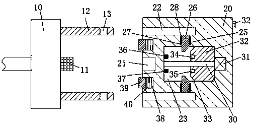
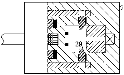
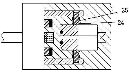
[0018] refer to Figure 1-4 The shown new energy vehicle device includes a charging gun connected to the new energy vehicle through a cable and a charging pile connected to the mains. The charging gun includes a handle 10, and the right end surface of the handle 10 is Two inserting arms 12 are provided at the front and rear ends of the front and rear sides of each other, and a locking groove 13 is provided at the right end of each of the two inserting arms 12, and a contact rod 11 is provided at the middle end of the right end surface of the handle 10. , the charging pile body includes a casing 20, and a hook 32 is fixedly installed on the upper ...


PUM


Abstract

The invention disclose a new energy vehicle device. The device comprises a charging gun connected with a new energy vehicle through a cable and a charging pile body connected with mains supply; the charging gun comprises a hand-pinched piece, two insertion arms are symmetrically arranged at the front and rear ends of the right end surface of the hand-pinched piece, a locking groove is formed in the right end of each insertion arm, and a touch rod is arranged at the middle end of the right end surface of the hand-pinched piece; the charging pile body comprises a shell sleeve, a hook is fixedly installed on the upper portion of the right end surface of the shell sleeve, and an electrical connection hole which is provided with an end opening facing leftwards and connected with the touch rod in a matched mode is formed in the left end surface of the shell sleeve, and the front and rear ends of the left end surface of the shell sleeve are symmetrically provided with arm insertion grooves connected with the insertion arms in a matched mode. The new energy vehicle device is simple in structure and good in power supply stability, electric shock accidents are prevented from occurring when the charging gun is plugged in or pulled out, the safety of the new energy vehicle during charging is ensured, and the whole device runs reliably, the locking and unlocking operation of the insertion arms and the contact rod is convenient, the charging gun is pulled out conveniently, and more labor is saved.

Description

technical field [0001] The invention relates to the field of new energy vehicles, in particular to a new energy vehicle device. Background technique [0002] At present, the charging of new energy vehicles is to directly insert the contact rod connected to it into the power connection hole of the charging pile body and then turn on the power. It is more convenient, but the length of the cable between the contact rod and the new energy vehicle is different, and there is no other locking device to lock the contact rod after the contact rod is inserted into the power connection hole. It will cause the contact rod to be detached from the power connection hole, which will lead to a sudden power failure of the new energy vehicle, so that the service life of the new energy vehicle will be reduced, and if it is serious, it will directly cause the burning of the new energy vehicle. Therefore, the existing The plug-in fit between the contact rod and the power connection hole has inst...

Claims


Application Information

Patent Timeline
Patent Type & Authority Patents(China)
IPC IPC(8): B60L11/18
CPCB60L53/16B60L53/31Y02T10/70Y02T10/7072Y02T90/12Y02T90/14
Inventor 莫金连
Owner WM MOTOR TECH GRP CO LTD
Why Eureka
Try Eureka