Method and device in UE and base station for multi-antenna transmission

A technology of multi-antenna transmission and base station, applied in radio transmission system, transmission system, wireless communication and other directions, can solve the problems of power consumption and occupation of air interface resources, etc.

Active Publication Date: 2020-12-25
SHANGHAI LANGBO COMM TECH CO LTD
View PDF4 Cites 0 Cited by
  • Summary
  • Abstract
  • Description
  • Claims
  • Application Information

AI Technical Summary

Problems solved by technology

[0004] In a massive MIMO system, the base station can determine the beam serving the UE through the report of the UE, but the mobility of the UE will cause the base station to switch the beam serving the UE according to the report of the UE, and the frequent reporting of the UE not only occupies air interface resources Moreover, power consumption and frequent switching of base stations will also bring the operating burden of the system

Method used


Image

  • Method and device in UE and base station for multi-antenna transmission
  • Method and device in UE and base station for multi-antenna transmission
  • Method and device in UE and base station for multi-antenna transmission

Examples


Embodiment 1

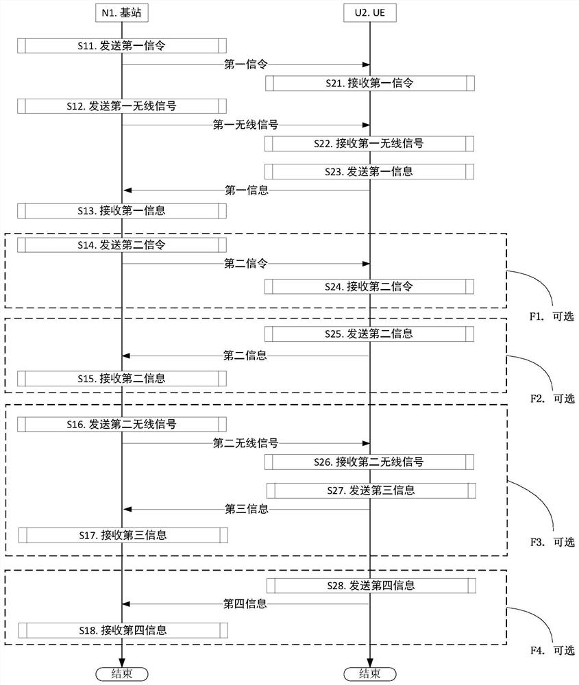
[0206]Example 1 illustrates the flow chart of wireless transmission, as attachedfigure 1 Shown. Attachedfigure 1 Among them, base station N1 is the serving cell maintenance base station of UE U2. Attachedfigure 1 , The steps in block F1, block F2, block F3 and block F4 are optional.

[0207]For N1, send the first signaling in step S11; send the first wireless signal in step S12; receive the first information in step S13; send the second signaling in step 14; receive the second information in step S15 ; Send the second wireless signal in step S16; receive the third information in step S17; receive the fourth information in step S18.

[0208]For U2, the first signaling is received in step S21; the first wireless signal is received in step S22; the first information is sent in step S23; the second signaling is received in step S24; the second information is sent in step S25 ; In step S26, the second wireless signal is received; in step S27, the third information is sent; in step S28, the fou...

Embodiment 2

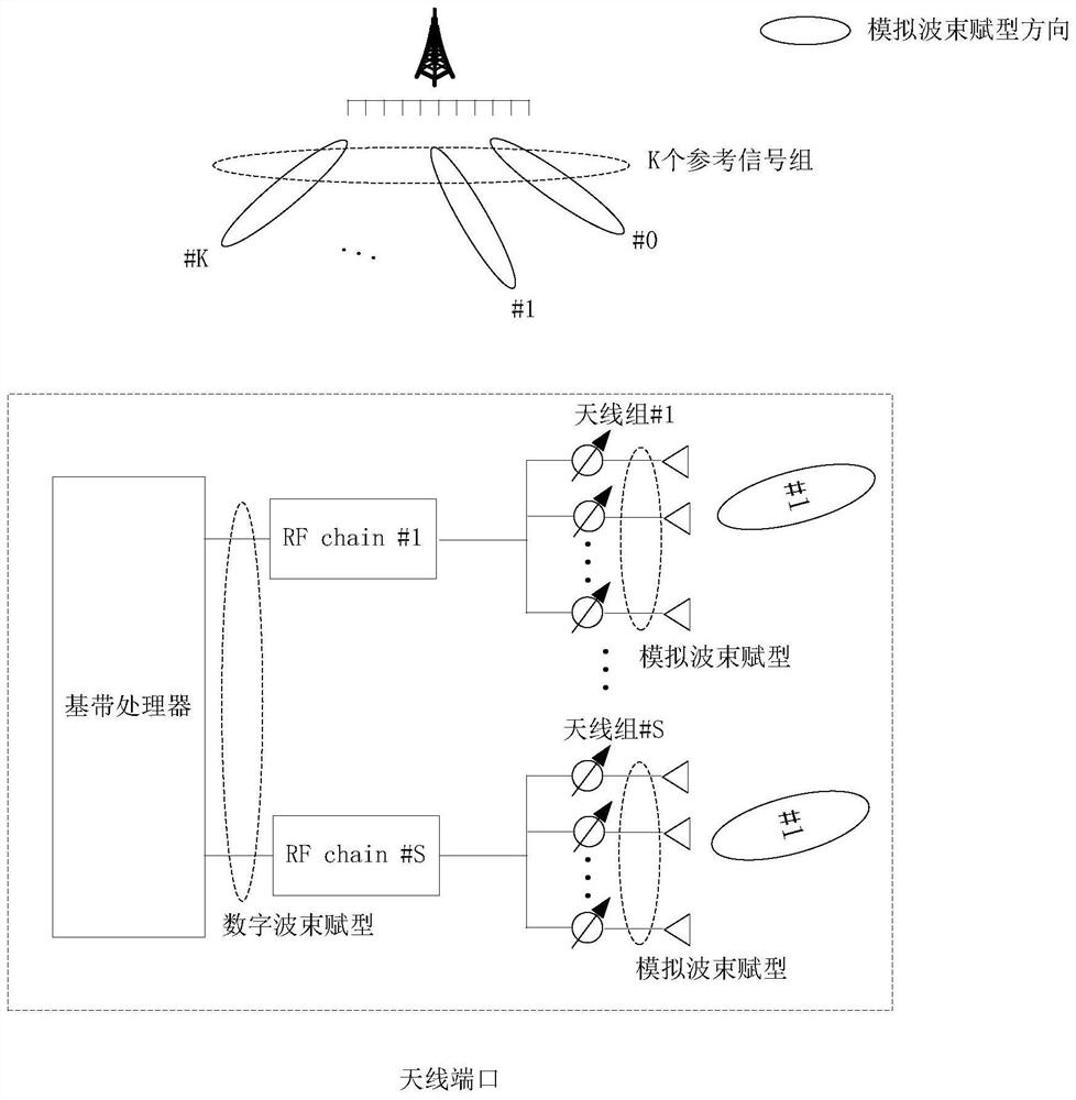
[0226]Embodiment 2 illustrates the schematic diagram of analog beamforming of K reference signal groups, as shown in the attached file.figure 2 Shown.

[0227]In Embodiment 2, the K reference signal groups and K antenna port groups have a one-to-one correspondence. The number of reference signals in the reference signal group is equal to the number of antenna ports in the corresponding antenna port group.

[0228]In Embodiment 2, the physical antenna corresponding to one antenna port is divided into S antenna groups, and each antenna group includes multiple antennas. The S is a positive integer. The antenna port is formed by superimposing multiple antennas in the S antenna groups through antenna virtualization, and the mapping coefficients from the multiple antennas in the S antenna groups to the antenna port constitute a beamforming vector. One of the antenna groups is connected to the baseband processor through an RF (Radio Frequency, radio frequency) link (Chain). One of the beamformin...

Embodiment 3

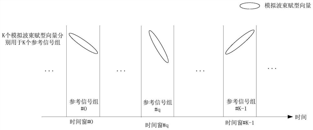
[0234]Embodiment 3 illustrates the timing diagram of K reference signal groups, as attachedimage 3 Shown.

[0235]In Embodiment 3, K antenna port groups correspond to K reference signal groups. The time domain resources occupied by any two reference signal groups in the K reference signal groups are orthogonal. The analog beamforming vectors corresponding to any two reference signal groups in the K reference signal groups cannot be considered the same. The K reference signal groups occupy K time windows. The K time windows are orthogonal in the time domain.

[0236]As a sub-example 1 of example 3, attachedimage 3 One transmission of the K reference signal groups is described. The K reference signal groups are sent periodically.

[0237]As a sub-embodiment 2 of embodiment 3, within a time window, the reference signal adopts a CSI-RS pattern.

[0238]As a sub-embodiment 3 of embodiment 3, within a time window, the reference signal adopts the pattern of SS.


PUM


Abstract

The invention discloses a method and device in UE and base station for multi-antenna transmission. The UE sequentially receives the first signaling, receives the first radio signal, and sends the first information. Wherein, the first signaling is used to determine at least one of {target antenna port group, target threshold}. K antenna port groups are used to send the first wireless signal. The K antenna port groups respectively correspond to K channel quality values. The target channel quality is a channel quality value corresponding to the target antenna port group among the K channel quality values. The first information is used to determine whether there is a channel quality value greater than the sum of the target channel quality plus the target threshold among the K channel quality values. The present invention supports the UE to notify the serving base station whether beam switching or related reporting is required according to the measurement, and the serving base station can reduce the frequent reporting of the UE by setting the target threshold, thereby reducing the air interface resources and power occupied by the UE to report the beam information.

Description

Technical field[0001]The invention relates to a multi-antenna transmission scheme in a wireless communication system.Background technique[0002]Massive MIMO (Multi-Input Multi-Output) has become a research hotspot in the next generation of mobile communications. In massive MIMO, multiple antennas are beam-forming to form a narrow beam pointing to a specific direction to improve communication quality. Massive MIMO can also use multiple antennas to form different directions and serve multiple users at the same time, so as to improve the throughput of the massive MIMO system and reduce the transmission delay.[0003]According to the discussion of 3GPP (3rd Generation Partner Project) RAN1 (RadioAccess Network, radio access network), a hybrid beamforming that combines analog beamforming and digital precoding Hybrid beamforming has become an important research direction of NR (New Radiotechnology) systems.[0004]In a massive MIMO system, the base station can determine the beam served by the ...

Claims


Application Information

Patent Timeline
Patent Type & Authority Patents(China)
IPC IPC(8): H04B7/0408H04B7/0413H04W72/12
CPCH04B7/0408H04B7/0413H04W72/54
Inventor 张晓博
Owner SHANGHAI LANGBO COMM TECH CO LTD
Why Eureka
Try Eureka