A kind of bus lifting ring hand-pulled electric energy collector

A technology for electric energy collection and buses, which is applied to vehicle parts, machines/engines, special positions of vehicles, etc., can solve problems such as single structure of lifting rings and handles, low bearing capacity, etc., to reduce bacterial pollution, increase service life, and improve sanitation status effect

CN108263263BActive Publication Date: 2020-04-14QINGHAI QIANXUN INFORMATION TECH CO LTD
14 Cites 0 Cited by

Patent Information

Authority / Receiving Office
CN · China
Patent Type
Patents(China)
Current Assignee / Owner
Publication Date
2020-04-14

Smart Images

  • Figure 1
    Figure 1
  • Figure 2
    Figure 2
  • Figure 3
    Figure 3
Patent Text Reader

Abstract

The invention discloses a bus hanging ring hand-pulled power collector. A rotating magnet ring is arranged on the inner circumference of an annular magnet drum, and a threaded transmission mechanism is arranged on the outer circumference of the annular magnet drum. The threaded transmission mechanism is composed of a transmission thread screw, a transmission sliding block, a connecting frame and amini fan. A power generation frame is arranged at the bottom of the connecting frame, and a hand-pressed power generation device is arranged at the bottom of the power generation frame in a clamped mode. According to the bus hanging ring hand-pulled power collector, the mini fan and the rotating magnet ring are separately connected with the transmission thread screw, the mechanical efficiency isgreatly improved, and the energy generated when a bus body shakes is used effectively; the mini fan can generate a tiny amount of wind against the palm of a human hand, and the bacterial pollution caused by hand sweating is reduced; certain electric energy can be output when the palm holds and presses the hand-pressed power generation device, and the energy-saving purpose is achieved; and the bushanging ring hand-pulled power collector can be widely used in the bus industry and is beneficial to improving the city image.
Need to check novelty before this filing date? Find Prior Art

Description

technical field

[0001] The invention relates to the technical field of public transportation auxiliary accessories, in particular to a hand-pulled electric energy collector for a bus suspension ring. Background technique

[0002] The bus is one of the main means of transportation for the convenience of the public. The bus ring is one of the important accessories in the bus compartment. The bus ring can provide certain help for passengers to stand firmly. Most of the rings are made of ABS engineering plastics. According to the shape, it can be divided into square, triangle and ellipse. The main problem of the existing bus ring is the problem of the man-machine of the product, which cannot meet the needs of the man-machine, especially the health demand, safety demand and comfort demand, and In addition to the disadvantages of boring shape, monotonous color, and single function, the existing bus rings also have the following problems. The existing bus rings are relatively shaki...

Examples

Embodiment Construction

[0016] The following will clearly and completely describe the technical solutions in the embodiments of the present invention with reference to the accompanying drawings in the embodiments of the present invention. Obviously, the described embodiments are only some, not all, embodiments of the present invention. Based on the embodiments of the present invention, all other embodiments obtained by persons of ordinary skill in the art without making creative efforts belong to the protection scope of the present invention.

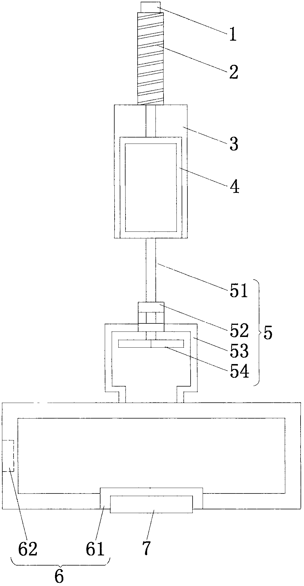
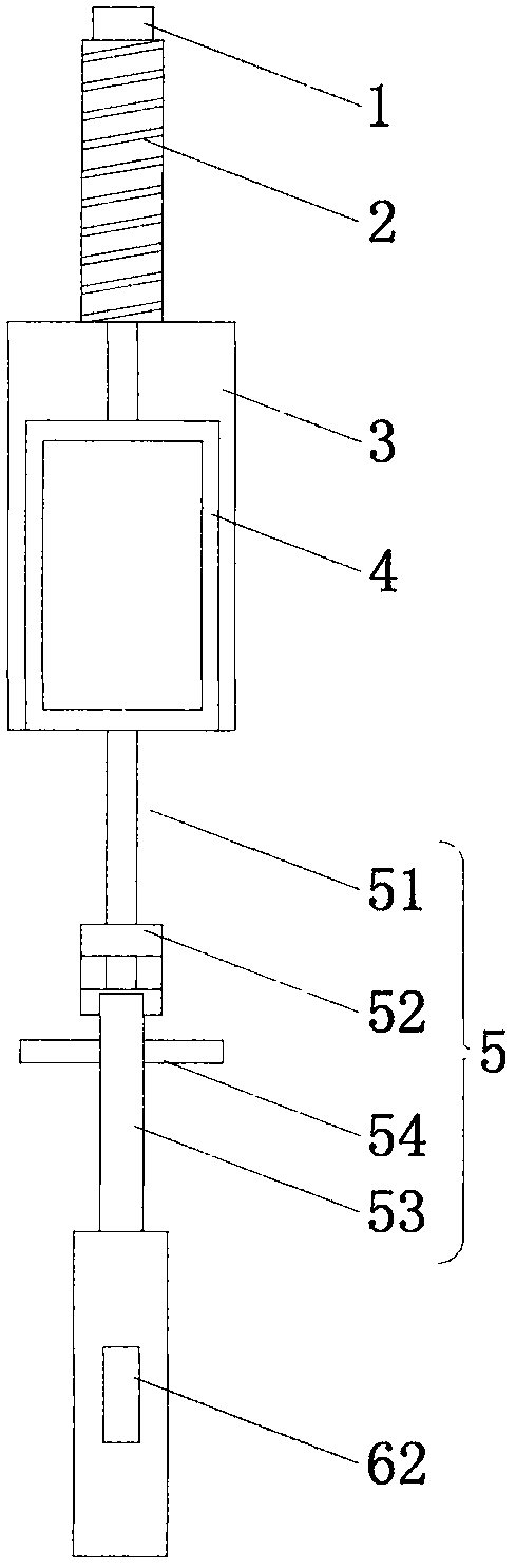
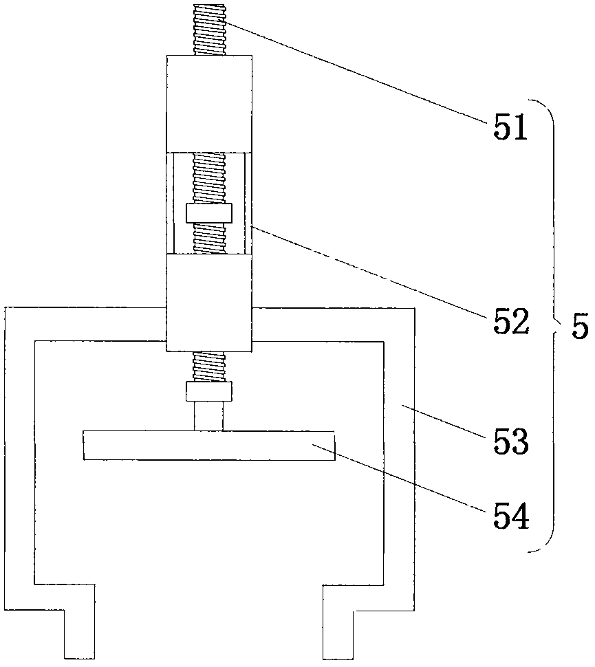
[0017] see Figure 1-3 , a hand-pulled electric energy collector with a bus ring, comprising a positioning fixing seat 1 and a spiral telescopic height adjustment mechanism 2, one side of the spiral telescopic height adjustment mechanism 2 is provided with a positioning fixing seat 1, and the positioning fixing seat 1 is fixedly installed on the spiral telescopic At the center of the top of the height adjustment mechanism 2, one end of the spiral telescopic he...