Dust collection device for urban public places

A technology for public places and dust removal devices, which is applied in the installation of vacuum cleaners, electrical equipment, and cleaning equipment. It can solve problems such as loose plugs and sockets, affecting dust removal efficiency, and power failure of vacuum cleaners, so as to reduce potential safety hazards and ensure electricity safety. High safety, the effect of preventing electric shock accidents

Inactive Publication Date: 2018-07-13
珠海句宸光电科技有限公司
View PDF0 Cites 0 Cited by
  • Summary
  • Abstract
  • Description
  • Claims
  • Application Information

AI Technical Summary

Problems solved by technology

[0002] In some public places such as bus stations, railway stations, etc., due to the large flow of people, a lot of dust will be generated. If these dusts are not disposed of in time, the air quality will be reduced, and therefore, it will affect people's health. As we all know, the traditional dust removal method is to use a vacuum cleaner to absorb the dust on the ground and corners. Traditional vacuum cleaners generally have long wires. After matching the power plug with the socket on the wall, the vacuum cleaner can be energized. Carry out vacuuming operations, but in public places, the wires are often kicked or tripped by passing pedestrians, which can make the plug and socket loose or even fall off, so the power of the vacuum cleaner can be cut off, which can affect the dust removal efficiency, and In public places, sockets are also easily occupied by people, and electric shock accidents are also prone to occur

Method used


Image

  • Dust collection device for urban public places
  • Dust collection device for urban public places
  • Dust collection device for urban public places

Examples


Embodiment Construction

[0020] All features disclosed in this specification, or steps in all methods or processes disclosed, may be combined in any manner, except for mutually exclusive features and / or steps.

[0021] Any feature disclosed in this specification (including any appended claims, abstract and drawings), unless expressly stated otherwise, may be replaced by alternative features which are equivalent or serve a similar purpose. That is, unless expressly stated otherwise, each feature is one example only of a series of equivalent or similar features.

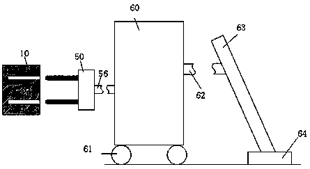
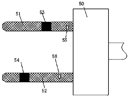
[0022] Such as Figure 1 to Figure 3As shown, a dust removal device for urban public places of the present invention includes a dust suction cylinder 60, an operating handle 63 connected to the dust suction cylinder 60 through a dust suction hose 62, and an operating handle 63 connected to the dust suction cylinder 60 through a wire 56. The power plug 50 connected to the dust cylinder 60 and the power supply socket 10 fixedly installed on the...


PUM


Abstract

The invention discloses a dust collection device for urban public places. The dust collection device comprises a dust collection cylinder, an operating handle rod connected with the dust collection cylinder through a dust collection hose, a powering-on plug connected with the dust collection cylinder through a wire and a power supply base fixedly installed on the wall and matched with the powering-on plug; a ground brush communicated with the dust collection hose is fixedly installed at the bottom end of the operating handle rod, an upper plugging groove and a lower plugging groove are symmetrically formed in the power supply base up and down, a first upper sliding groove and a second upper sliding groove with openings formed towards the upper plugging groove are formed in the bottom wallof the upper inserting groove, a first lower sliding groove and a second lower sliding groove are formed in the top wall of the lower inserting groove, the first lower sliding groove is located on theleft side of the first upper sliding groove, the second lower sliding groove is located between the first upper sliding groove and the second upper sliding groove, a first permanent magnet block capable of sliding up and down and a first sliding block capable of sliding up and down are installed in the first upper sliding groove and the second upper sliding groove respectively, and a first powersupply head connected with the city power is fixedly installed on the bottom wall of the first upper sliding groove.

Description

technical field [0001] The invention relates to the field of dust removal for environmental protection, in particular to a dust removal device for urban public places. Background technique [0002] In some public places such as bus stations, railway stations, etc., due to the large flow of people, a lot of dust will be generated. If these dusts are not disposed of in time, the air quality will be reduced, and therefore, it will affect people's health. As we all know, the traditional dust removal method is to use a vacuum cleaner to absorb the dust on the ground and corners. Traditional vacuum cleaners generally have long wires. After matching the power plug with the socket on the wall, the vacuum cleaner can be energized. Carry out vacuuming operations, but in public places, the wires are often kicked or tripped by passing pedestrians, which can make the plug and socket loose or even fall off, so the power of the vacuum cleaner can be cut off, which can affect the dust remov...

Claims


Application Information

Patent Timeline
IPC IPC(8): A47L9/28
CPCA47L9/2889
Inventor 郭木彩
Owner 珠海句宸光电科技有限公司
Why Eureka
Try Eureka