Textile fabric dyeing equipment

A technology for dyeing equipment and textiles, which is applied in the processing of textile materials, equipment configuration, textiles and papermaking, and textile materials processing. It can solve problems such as uneven dyeing and affect the uniformity of dyeing, and achieve the effect of avoiding uneven color.

Active Publication Date: 2018-07-13
嘉兴市永泰五金塑料有限责任公司
View PDF6 Cites 21 Cited by
  • Summary
  • Abstract
  • Description
  • Claims
  • Application Information

AI Technical Summary

Problems solved by technology

[0006] In order to overcome the current disadvantages that the dyes will precipitate when dyeing the cloth, which will lead to uneven dyeing, and the upper and lower layers of the cloth will be exposed to dyes of different depths during the dyeing process, which will affect the

Method used


Image

  • Textile fabric dyeing equipment
  • Textile fabric dyeing equipment
  • Textile fabric dyeing equipment

Examples


Embodiment 1

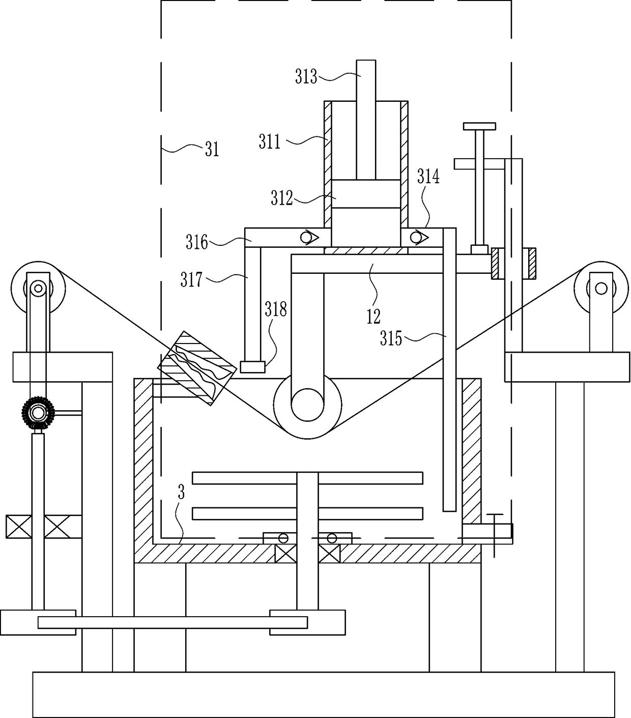
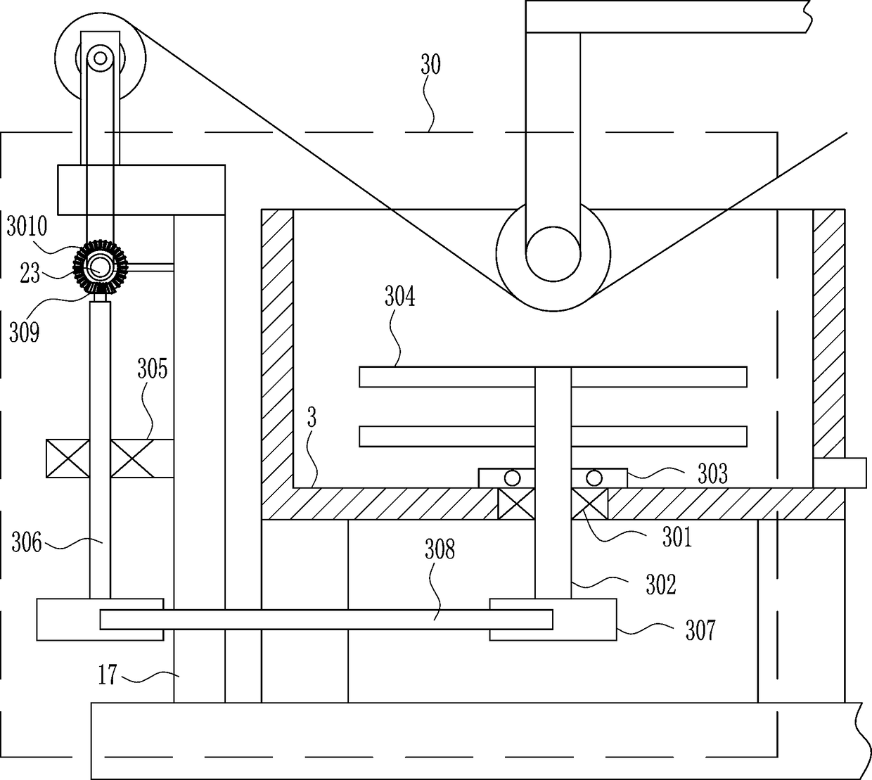
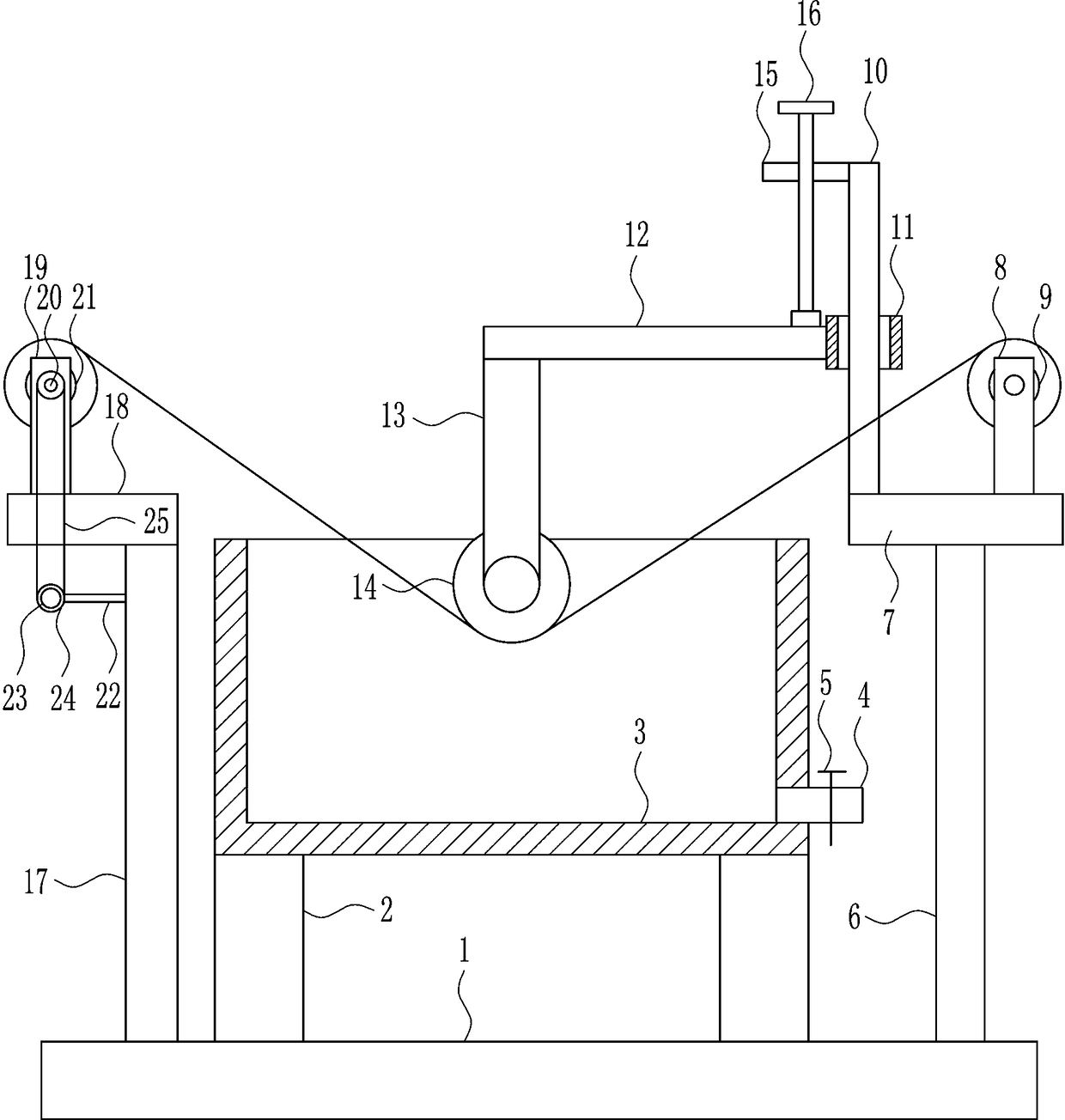
[0028] A kind of textile cloth dyeing equipment, such as Figure 1-5 As shown, it includes a bottom plate 1, a bracket 2, a dye box 3, a feeding pipe 4, a valve 5, a first support plate 6, a first mounting plate 7, a first connecting rod 8, a first set of wheels 9, a guide rail 10, Guide sleeve 11, second connecting rod 12, fixed rod 13, roller 14, nut 15, screw rod 16, second support plate 17, second mounting plate 18, third connecting rod 19, rotating shaft 20, second set wheel 21, The fourth connecting rod 22, the electric wheel 23, the first runner 24 and the first transmission bar 25, the left and right sides on the bottom plate 1 are connected with the support 2, the dye box 3 is connected between the upper ends of the support 2, and the right side of the dye box 3 The lower side is connected with a feeding pipe 4, the feeding pipe 4 is connected with a valve 5, the bottom plate 1 is connected with a first support plate 6 on the right side, the upper end of the first sup...

Embodiment 2

[0030] A kind of textile cloth dyeing equipment, such as Figure 1-5 As shown, it includes a bottom plate 1, a bracket 2, a dye box 3, a feeding pipe 4, a valve 5, a first support plate 6, a first mounting plate 7, a first connecting rod 8, a first set of wheels 9, a guide rail 10, Guide sleeve 11, second connecting rod 12, fixed rod 13, roller 14, nut 15, screw rod 16, second support plate 17, second mounting plate 18, third connecting rod 19, rotating shaft 20, second set wheel 21, The fourth connecting rod 22, the electric wheel 23, the first runner 24 and the first transmission bar 25, the left and right sides on the bottom plate 1 are connected with the support 2, the dye box 3 is connected between the upper ends of the support 2, and the right side of the dye box 3 The lower side is connected with a feeding pipe 4, the feeding pipe 4 is connected with a valve 5, the bottom plate 1 is connected with a first support plate 6 on the right side, the upper end of the first sup...

Embodiment 3

[0033] A kind of textile cloth dyeing equipment, such as Figure 1-5 As shown, it includes a bottom plate 1, a bracket 2, a dye box 3, a feeding pipe 4, a valve 5, a first support plate 6, a first mounting plate 7, a first connecting rod 8, a first set of wheels 9, a guide rail 10, Guide sleeve 11, second connecting rod 12, fixed rod 13, roller 14, nut 15, screw rod 16, second support plate 17, second mounting plate 18, third connecting rod 19, rotating shaft 20, second set wheel 21, The fourth connecting rod 22, the electric wheel 23, the first runner 24 and the first transmission bar 25, the left and right sides on the bottom plate 1 are connected with the support 2, the dye box 3 is connected between the upper ends of the support 2, and the right side of the dye box 3 The lower side is connected with a feeding pipe 4, the feeding pipe 4 is connected with a valve 5, the bottom plate 1 is connected with a first support plate 6 on the right side, the upper end of the first sup...


PUM


Abstract

The invention relates to textile processing equipment, in particular to textile fabric dyeing equipment. The to-be-solved technical problem is to provide the textile fabric dyeing equipment capable ofstirring dye, so that no sediment occurs in the dye, the fabric is dyed uniformly, the upper and lower layers of the fabric both can be dyed with the dye at same depth in a dyeing process. In order to solve the above technical problem, the invention provides the textile fabric dyeing equipment, the textile fabric dyeing equipment comprises a bottom plate, brackets, a dye box, a discharging tube,a valve, a first supporting plate, a first mounting plate, a first connecting rod, and a first sleeve wheel, a guiding rail, a guiding sleeve, a second connecting rod and the like, wherein the left and right sides of the bottom plate both are connected to the brackets, and the dye box is connected between the upper ends of the brackets. According to the textile fabric dyeing equipment, the effectsthat the dye is stirred, so that no sediment occurs in the dye, the fabric is dyed uniformly, and the upper and lower layers of the fabric both can be dyed with the dye at same depth in the dyeing process are achieved.

Description

technical field [0001] The invention relates to a textile processing equipment, in particular to a textile cloth dyeing equipment. Background technique [0002] The original meaning of textile is taken from the general term of spinning and weaving, but with the continuous development and improvement of the textile knowledge system and subject system, especially after the emergence of non-woven textile materials and three-dimensional composite weaving technologies, textile is not only the traditional spinning and weaving Weaving also includes non-woven technology, three-dimensional weaving technology, electrostatic nano-netting technology, etc. [0003] At present, when processing textiles, especially when dyeing fabrics, most of the fabrics are directly dyed in the dyeing vat, but the dyes in the dyeing vat may precipitate, which will cause the fabric to be dyed. The dyeing of the fabric is uneven, and during the dyeing process, the upper and lower layers of the fabric come...

Claims


Application Information

Patent Timeline
IPC IPC(8): D06B3/10D06B1/02D06B23/02D06B23/04D06B23/20D06B3/34
CPCD06B1/02D06B3/10D06B3/34D06B23/021D06B23/023D06B23/04D06B23/205
Inventor 邱有萍
Owner 嘉兴市永泰五金塑料有限责任公司
Why Eureka
Try Eureka