A Self-pitching Controlled Blade Turbine Optimized Based on Traditional Wells Turbine

A Wells-style, pitch control technology, applied in the direction of machines/engines, mechanical equipment, ocean energy power generation, etc., can solve the problems of turbine performance deterioration, narrow working range, low peak efficiency, etc., and achieve good self-starting characteristics, The effect of high working efficiency and low working speed

Active Publication Date: 2019-12-27
OCEAN UNIV OF CHINA
View PDF7 Cites 0 Cited by
  • Summary
  • Abstract
  • Description
  • Claims
  • Application Information

AI Technical Summary

Problems solved by technology

Although the traditional impulse turbine has good start-up performance, its peak efficiency is low, and it is more suitable for sea areas with poor wave conditions. power loss
The traditional Wells-type turbine has the advantages of simple structure and high peak efficiency, and is suitable for sea areas with good wave conditions. Efficiency, once stalled, the huge reduction in torque makes the performance of the turbine deteriorate instantly
[0005] The existing Wells-type turbines are fixed blades, that is, the moving blades are symmetrically distributed along the center line of the hub rotation direction, generally at 90° to the center line, fixed on the hub and cannot be freely deflected

Method used


Image

  • A Self-pitching Controlled Blade Turbine Optimized Based on Traditional Wells Turbine
  • A Self-pitching Controlled Blade Turbine Optimized Based on Traditional Wells Turbine
  • A Self-pitching Controlled Blade Turbine Optimized Based on Traditional Wells Turbine

Examples


Embodiment 1

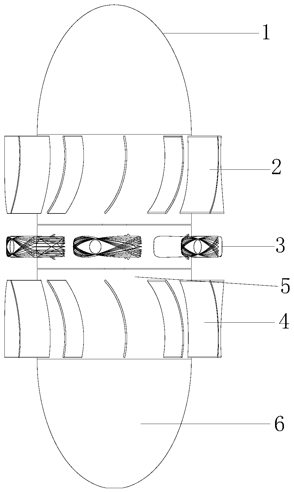
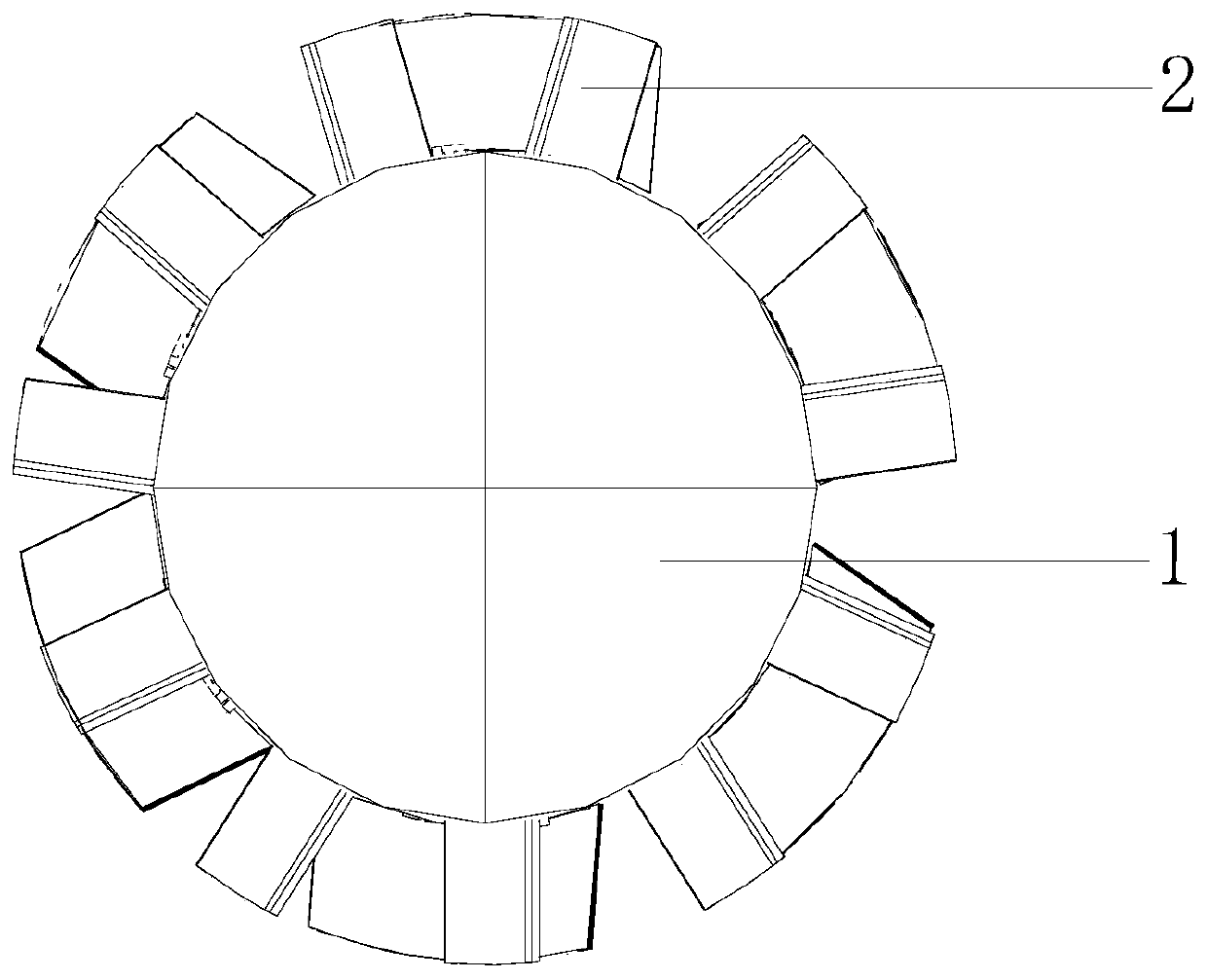
[0036] Example 1, such as Figure 2-5 As shown, this embodiment discloses a self-pitching control vane turbine optimized based on a traditional Wells-type turbine. The hub heads 1 and 6 of the mouth, the moving blade wheel 11 that can rotate around the hub is nested on the hub, such as Image 6As shown, two or more moving blades 3 are evenly arranged on the outer wall of the moving blade wheel along the circumferential direction. The upper and lower positions are also provided with a limit point 14, so that each moving blade can swing freely around its pivot between the angle γo set by the upper limit point and the angle γi set by the lower limit point. The wheel disc of the moving blade wheel is provided with a shaft sleeve 12 with a keyway, and the shaft sleeve is installed with a turbine shaft 8 that extends out of the hub head on one side and can rotate synchronously with the moving blade wheel. They are all connected by a bearing 7 to ensure their smooth rotation, and a...


PUM


Abstract

The invention discloses a self-pitching control blade turbine optimized based on a traditional Wells turbine. The self-pitching control blade turbine comprises a tubular hub; hub heads are mounted onthe two sides of the hub correspondingly; a movable blade wheel which can rotate around the hub is arranged on the hub in a nested mode; two or more movable blades are evenly arranged on the outer wall of the movable blade wheel in the circumferential direction; the movable blades are hinged to the movable blade wheel through pivots; a shaft sleeve with a key groove is arranged on a wheel disc ofthe movable blade wheel; a turbine shaft is mounted on the shaft sleeve, wherein one side of the turbine shaft extends out of the hub heads, and the turbine shaft can synchronously rotate with the movable blade wheel; and the upper side and the lower side of the movable blade wheel are further each provided with a circle of flow guiding blade set in the circumferential direction of the hub. According to the self-pitching control blade turbine, the movable blades can freely swing between an upper limiting point and a lower limiting point around the pivots of the movable blades, so that the deflection angle is autonomously changed according to the size and direction of a coming flow, in this way, the mounting angles of the movable blades can be changed at any time at different stages of a period of waves, and the period average efficiency of the turbine in the actual sea state is improved accordingly.

Description

technical field [0001] The invention belongs to the field of wave energy power generation, in particular to a self-pitching control blade type turbine optimized based on a traditional Wells type turbine in the field. Background technique [0002] As the most widely distributed ocean energy species, wave energy is almost not limited by location, and it is a marine renewable energy with a high degree of practicality and commercialization in the world today. Wave energy refers to the kinetic energy and potential energy of waves on the ocean surface, which is proportional to the square of the wave height, the period of motion of the wave, and the width of the wave-facing surface. Although wave energy is the most unstable energy in marine energy, its reserves in the world are very considerable, with a theoretical estimate of about 17TW·h per year, and it has the characteristics of no intermittence, little influence by day and night and seasons. [0003] According to the differen...

Claims


Application Information

Patent Timeline
Patent Type & Authority Patents(China)
IPC IPC(8): F03B13/22F03B11/00F03B15/00
CPCF03B11/00F03B13/22F03B15/00Y02E10/20Y02E10/30
Inventor 刘臻张莹史宏达黎明崔莹张晓霞孙立新许传礼张国梁
Owner OCEAN UNIV OF CHINA
Why Eureka
Try Eureka