Gas turbine engine

a technology of gas turbine engine and turbine blade, which is applied in the direction of machines/engines, efficient propulsion technologies, transportation and packaging, etc., can solve the problems of high weight, system add weight and complexity to engines, and increase the efficiency of turbines, reduce the diameter of turbines, and reduce the number of turbine stages

Inactive Publication Date: 2017-12-28
ROLLS ROYCE PLC
View PDF12 Cites 35 Cited by
  • Summary
  • Abstract
  • Description
  • Claims
  • Application Information

AI Technical Summary

Benefits of technology

[0015]The gas turbine engine gearbox may comprise a common input shaft coupled to the propulsor drive turbine, and first and second output shafts coupled to the first and second propulsors respectively. The gearbox may comprise a bevel gear arrangement. The gearbox may comprise a reduction gearbox, such that the input shaft rotates at a higher speed in use than the first and second output shafts. The gearbox may comprise an input:output ratio of between 1 and 5. It is has been found that the present invention is particularly advantageous where the gearbox comprises a reduction gearbox. Reduction gearboxes permit relatively high speed fan drive turbines to be employed, which increases the efficiency of the turbine, while reducing the number of turbine stages that are required, and reducing the diameter of the turbine, thereby reducing the weight and cost of the fan drive turbine. Consequently, the input shaft which interconnects the fan drive turbine and gearbox rotates at a relatively high speed. As a result, the torque carried by the input shaft is relatively low for a given power. This in turn means that a relatively thin, low diameter input shaft relative to the diameter of the core can be employed. Such shafts reduce weight further, but may result in bending or “whirl” modes of vibration. By employing a turbine engine core in which the fan drive turbine is provided as part of a second core module which is axially spaced from a first core module, the fan drive input shaft length is reduced, thereby ameliorating this issue.
[0016]Alternatively, the propulsor drive coupling may comprise a propulsor drive turbine driven electrical generator and first and second electrical motors coupled to respective propulsors, the generator being electrically coupled to the first and second motors. Consequently, the propulsor drive turbine can be situated remotely from the propulsors, without requiring a relatively heavy mechanical transmission system.

Problems solved by technology

Consequently, in order to provide adequate ground clearance with a high bypass ratio engine installed beneath a wing, long landing gear legs are required, which results in high weight, and may make egress from the aircraft in the event of an emergency difficult, in view of the long distance between the aircraft fuselage and the ground.
However, such systems add weight and complexity to engines, and are difficult to package in the limited space available.

Method used


Image

  • Gas turbine engine
  • Gas turbine engine
  • Gas turbine engine

Examples


Embodiment Construction

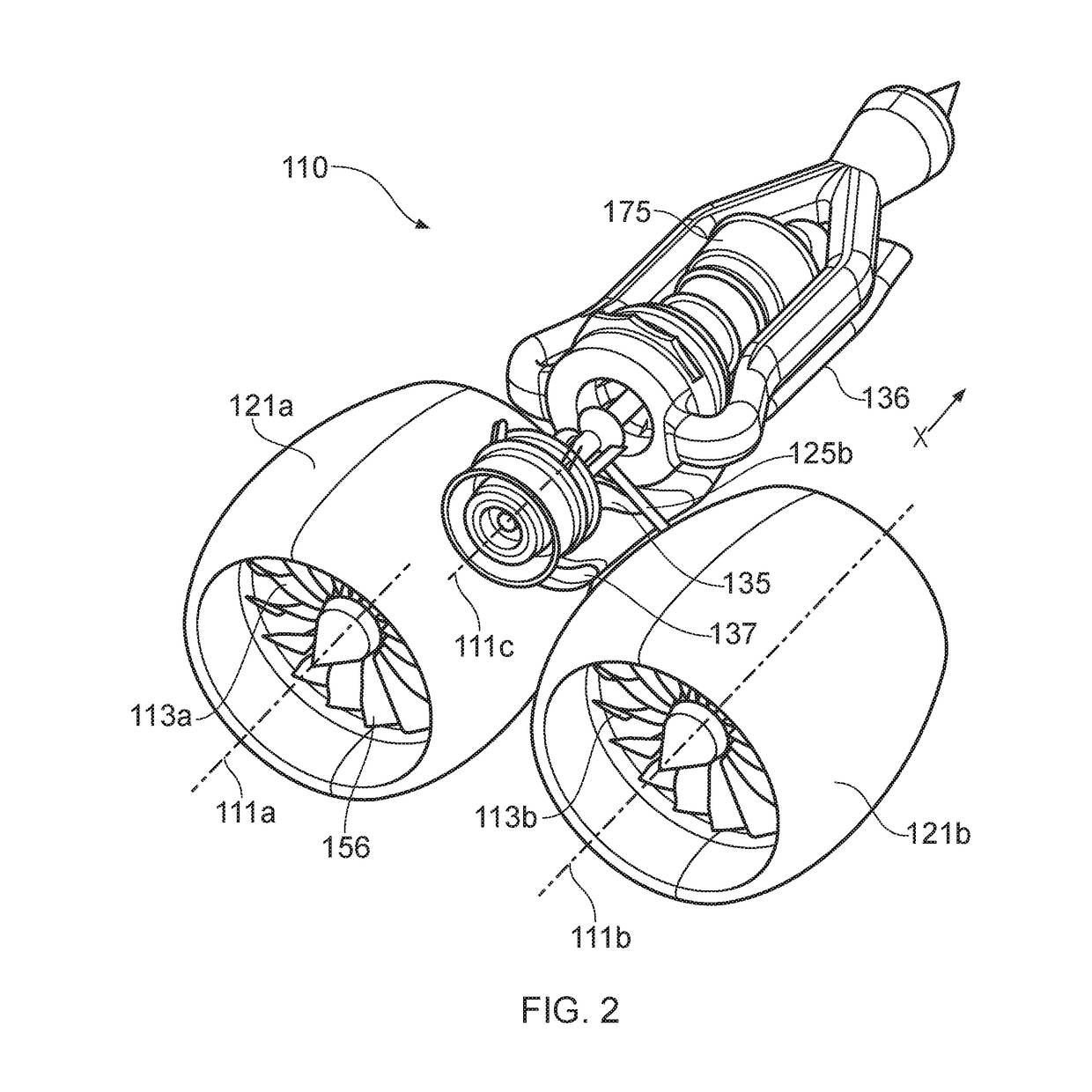
[0060]FIGS. 2, 3, 4 and 5 show a first gas turbine engine 110 in accordance with the present invention. The engine 110 comprises first and second ducted fans 113a, 113b provided within respective fan nacelles 121a and 121b. The fans 113a, 113b, and nacelles 121 are provided in a common plane, and rotate about parallel rotational axes 111a, 111b, but are non-coaxial, i.e. they do not occupy the same rotational axis. Alternatively, the fans 113a, 113b could be provided at different axial positions, or could be canted relative to one another.

[0061]Each fan 113a, 113b provides a propulsive air flow B which flows in an axial direction X, which defines a rearward direction. A forward direction is defined by an axial direction counter to this direction.

[0062]Each fan 113a, 113b comprises a plurality of fan blades 156. Each fan blade 156 is pivotable about a radially extending axis by a respective pitch change actuator 163a, 163b. The pitch change actuator may be of conventional constructio...


PUM


Abstract

An aircraft gas turbine engine (110) comprises first and second non-coaxial propulsors (113a, 113b), each propulsor (113a, 113b) being driven by a common gas turbine engine core (176) comprising a propulsor drive turbine (143) arranged to drive the first and second propulsors (113a, 113b) via a propulsor drive coupling (127). The core (176) further comprises a first core module (190) comprising a first compressor (129) and a first turbine (131) interconnected by a first shaft (177), and a second core module (191) comprising a second compressor (128) and the propulsor drive turbine (143) interconnected by a second shaft (127), the first and second core modules (190, 191) being axially spaced.

Description

FIELD OF THE INVENTION[0001]The present invention relates to a gas turbine engine, particularly to a gas turbine engine suitable for use on an aircraft, and an aircraft comprising a gas turbine engine.BACKGROUND TO THE INVENTION[0002]With reference to FIG. 1, a gas turbine engine is generally indicated at 10, having a principal and rotational axis 11. The engine 10 comprises, in axial flow series, an air intake 12, a propulsive fan 13, an intermediate pressure compressor 14, a high-pressure compressor 15, combustion equipment 16, a high-pressure turbine 17, and intermediate pressure turbine 18, a low-pressure turbine 19 and an exhaust nozzle 24. A nacelle 21 generally surrounds the engine 10 and defines both the intake 12 and a bypass exhaust nozzle 20.[0003]The gas turbine engine 10 works in the conventional manner so that air entering the intake 12 is accelerated by the fan 13 to produce two air flows: a first air flow A into the intermediate pressure compressor 14 and a second ai...

Claims


Application Information

Patent Timeline
Patent Type & Authority Applications(United States)
IPC IPC(8): B64D35/04F02C3/04B64D27/12F02C7/18B64D27/18B64D27/00
CPCB64D35/04B64D27/12B64D27/18F02C3/04F05D2260/213B64D2027/005F05D2220/323F05D2240/35F02C7/18F02C3/107F02C3/145F02C6/02F02C7/36Y02T50/60Y02T50/40B64D27/02B64D27/24F02C6/206F02C7/08F02C7/143F02K1/74F02K3/077F05D2220/76B64D2027/026B64D2221/00
Inventor BRADBROOK, STEPHEN J.
Owner ROLLS ROYCE PLC
Why Eureka
Try Eureka