System for sealing an inner retainer segment and support ring in a gas turbine and methods therefor

Inactive Publication Date: 2005-11-03
GENERAL ELECTRIC CO
View PDF18 Cites 36 Cited by
  • Summary
  • Abstract
  • Description
  • Claims
  • Application Information

AI Technical Summary

Benefits of technology

[0001] The present invention relates to apparatus and methods for sealing between the inner retainer segment and an inner platform rail of a nozzle segment in a gas turbine and particularly relates to seal assemblies for increas

Problems solved by technology

The sealing efficiency of nozzle chordal land seals is limited, however, by 1) an uneven sealing load along the seal land length caused by circumferential torque generated by the nozzle; 2) lack of flatness of the seal lands and support ring caused by thermal d

Method used


Image

  • System for sealing an inner retainer segment and support ring in a gas turbine and methods therefor
  • System for sealing an inner retainer segment and support ring in a gas turbine and methods therefor
  • System for sealing an inner retainer segment and support ring in a gas turbine and methods therefor

Examples


Embodiment Construction

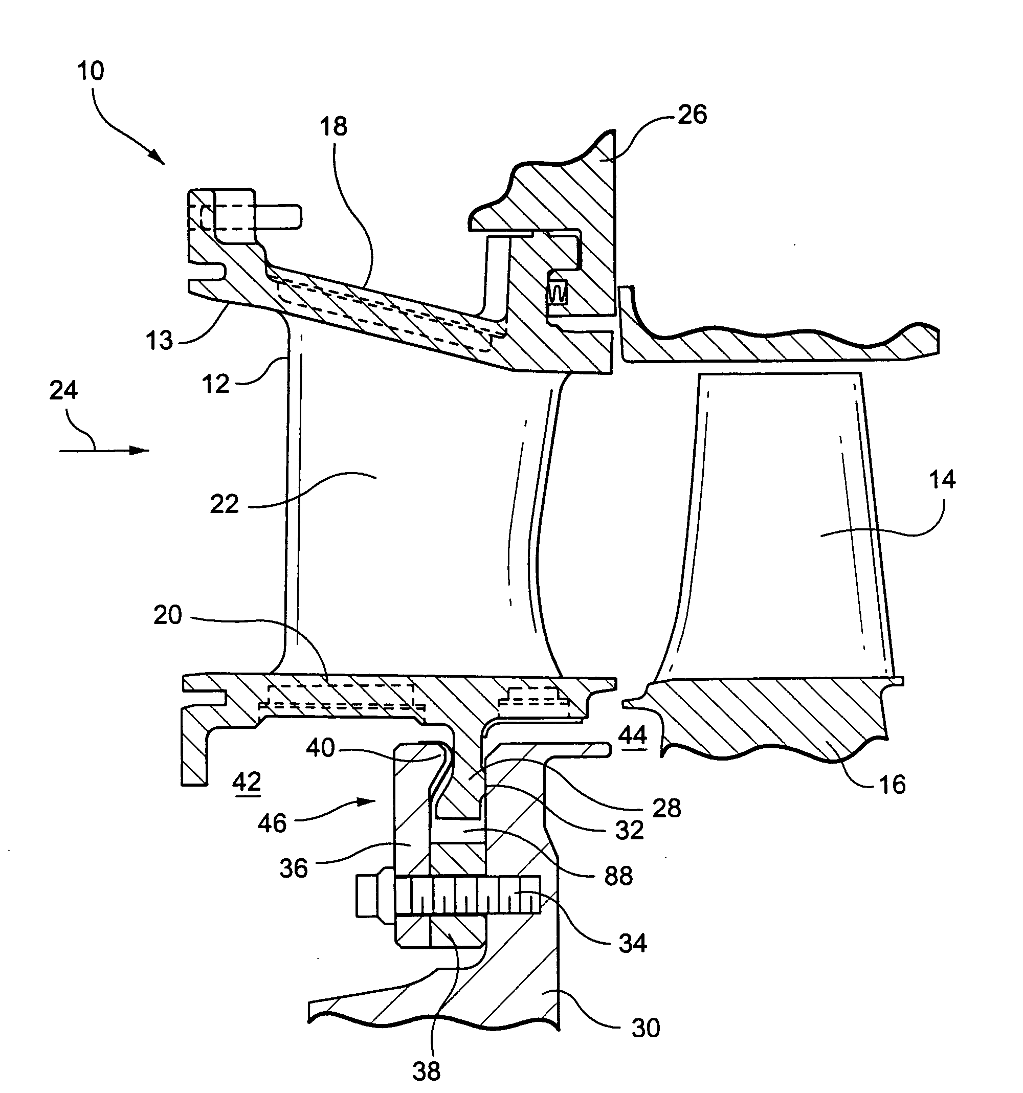
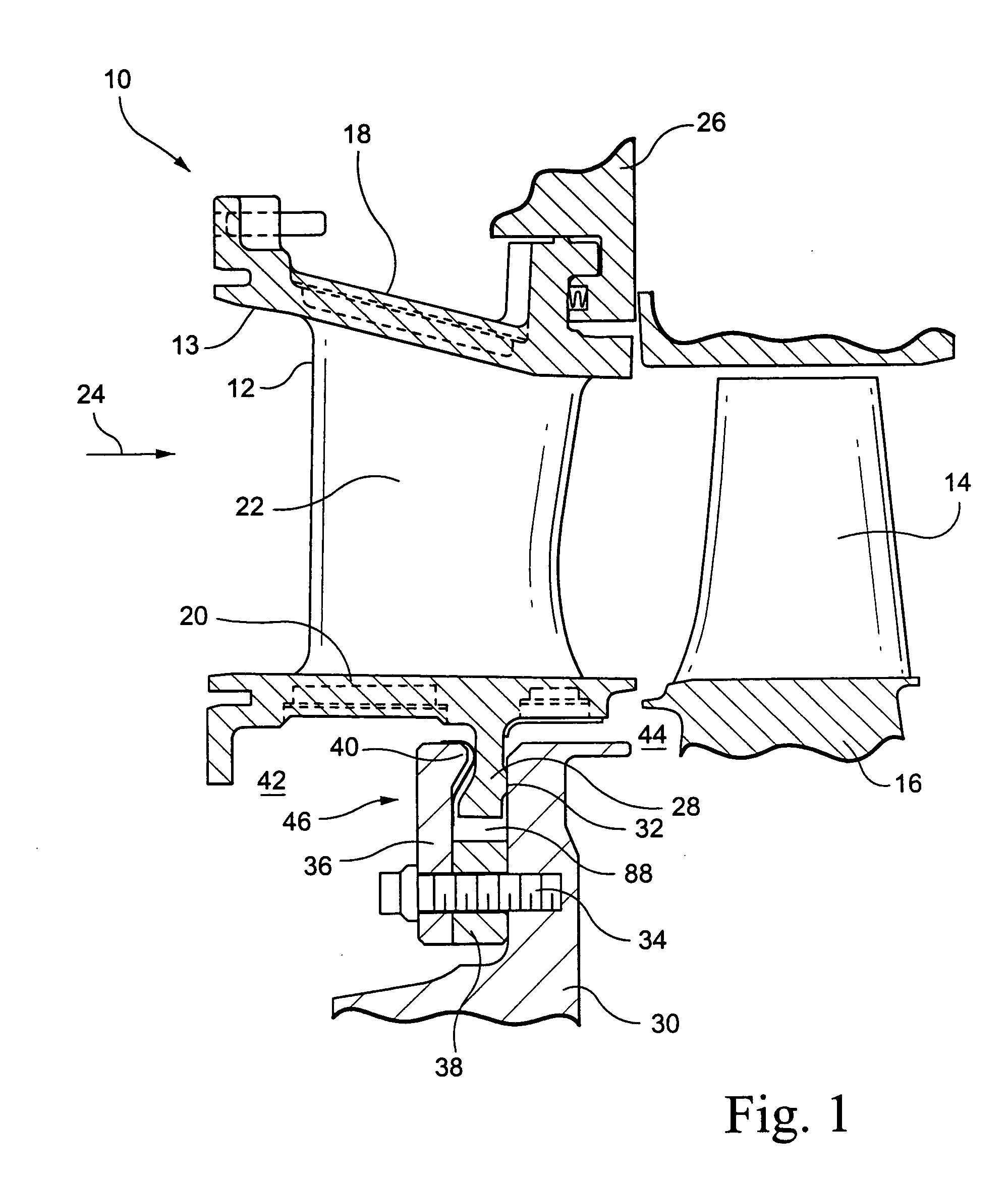
[0017] Referring now to the drawings, particularly to FIG. 1, there is illustrated a portion of a turbine, generally designated 10, including a first stage nozzle 12 and first stage buckets 14 forming part of a rotor 16. The nozzle 12 includes an outer band or platform 18, and an inner band or platform 20. The nozzle 12 is formed of a plurality of nozzle segments 13 each having an outer and inner band 18 and 20, respectively, with one or more vanes 22 extending therebetween. As is well known, the nozzle vanes 22 as well as the buckets 14 extend in the hot gas path of the turbine, the hot gas path having a flow direction designated by the arrow 24 in FIG. 1. The vanes 22 and buckets 14 are arranged in annular arrays about an axis of the turbine. The outer platform 18 of each nozzle segment is secured to an outer retaining ring 26. Each of the nozzle segments includes a radially inwardly directed inner platform rail 28, the aft face of which bears against an inner support ring 30 prec...


PUM


Abstract

Arcuate seal layers conforming with one another are disposed between inner retainer segments and inner rails of nozzle segments of a gas turbine. The layers are secured to the aft axial face of the segments and project radially outwardly to seal against the forward axial faces of the rails. The rear axial faces of the rails have chordal seals for sealing against the forward axial faces of the support rings. The seal layers have radial cuts misaligned with one another in an axial direction to preclude leakage flows through gaps formed by the cuts. Arcuate spacers are staggered circumferentially with the arcuate retainer segments whereby an intermediate pressure plenum is formed between the finger seals and chordal seals.

Description

BACKGROUND AND SUMMARY OF THE INVENTION [0001] The present invention relates to apparatus and methods for sealing between the inner retainer segment and an inner platform rail of a nozzle segment in a gas turbine and particularly relates to seal assemblies for increasing sealing and turbine engine efficiencies by reducing leakage between a high pressure region for supplying cooling air to the turbine nozzles and a forward rotor rim cavity including the hot gas path outboard of the rim cavity. [0002] In gas turbines, hot gases of combustion flow from combustors through first stage nozzles and buckets and through follow-on stages. The first stage nozzles typically include an annular array or assemblage of cast nozzle segments each containing one or more nozzle stator vanes per segment. Each nozzle segment also includes inner and outer platforms or bands spaced radially one from the other. Upon assembly of the nozzle segments into the turbine, the stator vanes are circumferentially spa...

Claims


Application Information

Patent Timeline
IPC IPC(8): F01D1/02F01D9/02
CPCF01D9/023
Inventor COIGN, ROBERT WALTERHUMANCHUK, DAVID JOHNFOSTER, GREGORY THOMASWORLEY, KEVIN LEE
Owner GENERAL ELECTRIC CO
Why Eureka
Try Eureka