Modular system for generating electricity from moving fluid

a technology of moving fluid and modular system, which is applied in the direction of hydro energy generation, non-positive displacement fluid engine components, liquid fuel engine components, etc., can solve the problems of inability to allow modular system installation, requiring relatively complex and consequently costly construction, and the least efficient of the three styles, etc., to achieve simple structure, easy to install and maintain, and convenient and economical construction.

Inactive Publication Date: 2009-01-29
PETROUNEVITCH EDOUARD
View PDF3 Cites 36 Cited by
  • Summary
  • Abstract
  • Description
  • Claims
  • Application Information

AI Technical Summary

Benefits of technology

[0050]The system's modularity allows it to be assembled by bolts, screws and conventional anchoring pieces. Such gives a time advantage for assembly and maintenance. The array of these modules may be arranged side by side, so as to intersect any cross sectional area of the flow nearly completely, thus providing versatile forms of hydroelectric power systems whic

Problems solved by technology

Clearly, devices such as these are simply too large for use in streams of shallow rivers.
Additionally, they fail to allow for modular system installation requiring relatively complex and consequently costly construction.
And, most importantly, these turbines are the least efficient of the three styles.
Firstly, the main problem with this type of equipment is the inherited conflict of interests between two forces: a gravitational force trying to keep the shatters opened, and an opposing frictional force trying to close the shatters on the frictional side of the disk. When the wind is not blowing, the shutters are opened by gravity. When the slow or modest wind is blowing, the shatters are only partially closed as the gravit

Method used


Image

  • Modular system for generating electricity from moving fluid
  • Modular system for generating electricity from moving fluid
  • Modular system for generating electricity from moving fluid

Examples


embodiment a

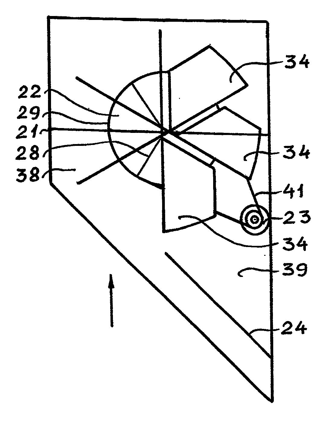
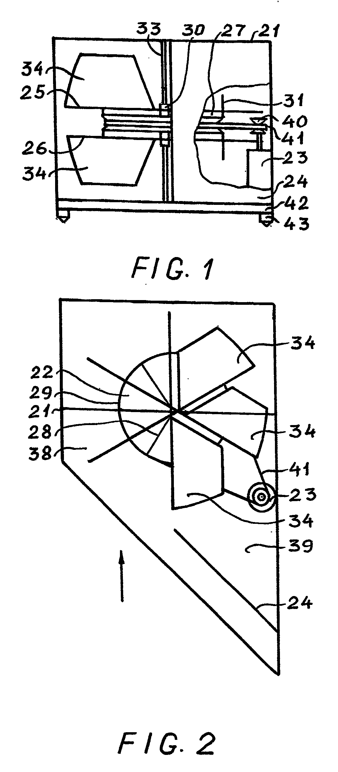
[0071]The embodiment A is the system assembly capable of harvesting the kinetic energy from unidirectional flow of water for producing electricity. The system comprises an array of interconnected submersible units or modules to harness water power. Each system module (see FIGS. 1 and 2) contains a water current energy converter positioned in a protecting housing 21 with proper bearings.

[0072]A converter consists of a detachable vertical axis hydro-turbine 22, the detachable electrical generator 23, and detachable water current deflector 24.

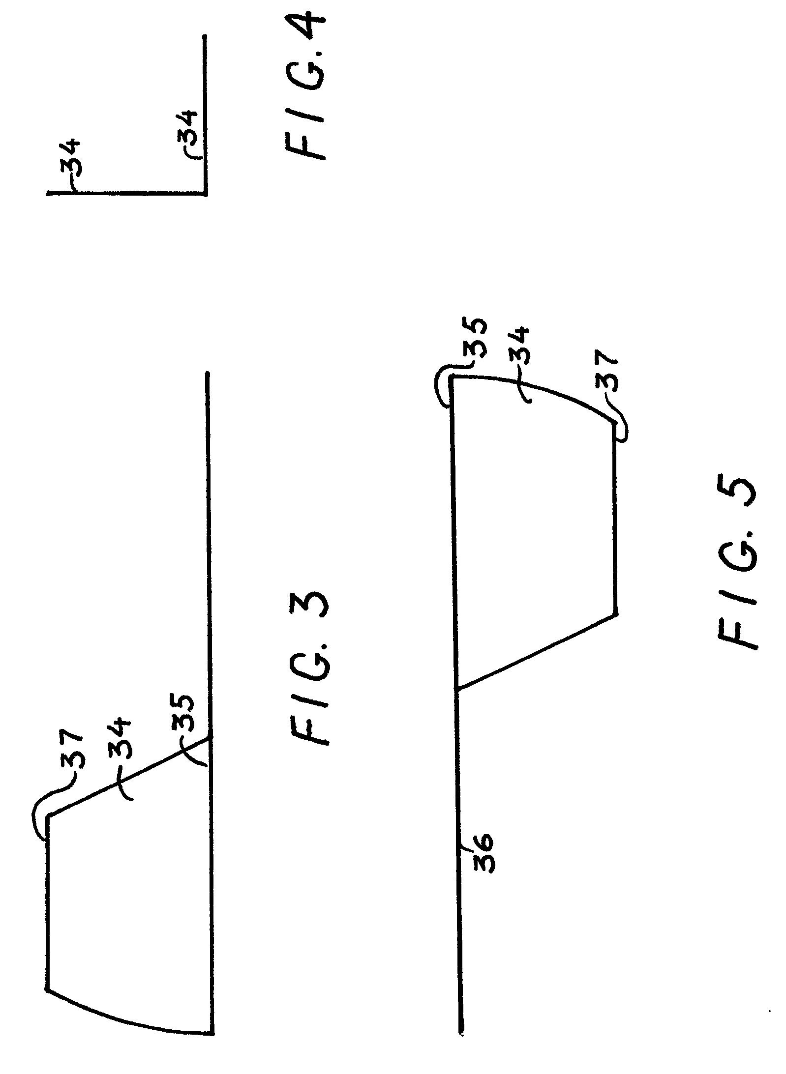
[0073]The turbine 22 is essentially a paddlewheel having an arrangement of two sets 25 and 26 of attached paddles with asymmetrically fixed blades to increase torque and power output. The first set 25 of paddles with floatable blades is located above the working wheel 27, as the second set 26 of paddles with sinkable blades is located below the working wheel 27. A plurality of radial spokes 28 connects the working wheel's rim 29 to the hub 30. Suc...

embodiment b

[0093]The embodiment B is the system assembly comprising an array of interconnected submersible units or modules capable of harvesting the kinetic energy of tides that alternate direction of their movement on 180 degrees. Each system unit or module (see FIG. 9) contains a water current energy converter positioned in a protecting housing 50.

[0094]A converter consists of a detachable vertical axis hydro-turbine 22, analogous to that described in the embodiment A, the detachable electrical generator 23, and two detachable flow deflectors 53 and 54.

[0095]Symmetrically located in inlet / outlet areas of the module, the flow deflectors 53 and 54 are secured to the housing in a pivotal manner. The free end of each flow deflector is able to rotate in the sector restricted by the filter panels 55, 56 and screen panels 57, 58 incorporated into protecting housing 50. The arrangement of the flow deflectors is such that they are urged by incoming flow of water to rotate toward the screen panels wh...

embodiment c

[0098]The embodiment C is the system assembly comprising an array of interconnected units or modules capable of harvesting the kinetic energy of wind.

[0099]Each system unit or module depicted in FIGS. 10 and 11 contains a wind energy converter positioned in a housing 60.

[0100]A converter consists of a detachable vertical axis turbine 61 with a set of paddles 62 located below the working wheel, and the detachable electrical generator 23, connected to the wheel's outer diameter (rim) 29, as shown in FIGS. 10 and 11.

[0101]The system module's housing 60 is a strong steel frame having a shape of the right square prism. Additionally, the housing includes the detachable screens to prevent collisions with birds.

[0102]This vertical axis wind turbine, illustrated separately in FIG. 12, works in a similar way as a turbine for water applications described in the embodiments A and B. The turbine's paddles and blades can be produced from any suitable lightweight and strong material, and are of th...


PUM


Abstract

A modular system for producing electricity from the channel, river, ocean or tidal water currents and wind is disclosed. The embodiments of the system comprise a set of interconnected modules. Each module contains a fluid flow energy converter positioned in a protecting housing. A converter consists of a vertical axis underwater hydro-turbine or wind turbine, connected to the electrical generator. The turbine is essentially a paddlewheel having an arrangement of attached paddles with mutually perpendicularly oriented asymmetric blades that are fixed to the poles at both ends. Such orientation of blades provides a positive feedback minimizing the blades' friction while maximizing a drag force and maximizing the turbine's efficiency. The electrical generator transforms the rotational energy of the turbine into electricity. An array of modules may be arranged side by side, thus providing versatile configurations of submersible hydroelectric or wind power systems, which are inexpensive to build, install and maintain.

Description

FIELD OF THE INVENTION[0001]This invention relates to modular systems for producing electricity from the kinetic energy present in flowing water or wind.BACKGROUND[0002]The renewable energy sources are important in order to guarantee a sustainable power production in the future. Hydropower is the largest and the most applied renewable energy source in the production of electricity. Today conventional hydropower is constrained by land use, environmental concerns and high up-front capitalization. The renewable energy technology, such as underwater hydrokinetic energy systems, is a valuable part of the overall solution.[0003]These systems are located beneath the water's surface and generate electricity from the kinetic energy present in flowing water. They may operate in rivers, manmade channels, tidal waters, or ocean currents. Hydrokinetic systems utilize the water stream's natural pathway. No dam or impoundment is needed, therefore there is no major civil work to change the landscap...

Claims


Application Information

Patent Timeline
IPC IPC(8): F03B13/10F03B13/26F03D9/00F03B3/12F03D11/00F03B11/08F03B13/12
CPCF03B13/264F03B17/062F03D3/067Y02E10/74F05B2240/40F05B2240/97Y02E10/28F05B2210/16Y10S415/906Y02E10/30Y02E10/20
Inventor PETROUNEVITCH, EDOUARD
Owner PETROUNEVITCH EDOUARD
Why Eureka
Try Eureka