Method for forming a heat dissipation device

Inactive Publication Date: 2010-04-20
THERMAL
View PDF22 Cites 17 Cited by
  • Summary
  • Abstract
  • Description
  • Claims
  • Application Information

AI Technical Summary

Benefits of technology

[0021]The structure is inexpensively built from the minimum necessary parts and provides advantage

Problems solved by technology

Various electrical semiconductor devices, such as large scale integrated circuits, voltage regulators, current switching devices, high speed or high current circuits an

Method used


Image

  • Method for forming a heat dissipation device
  • Method for forming a heat dissipation device
  • Method for forming a heat dissipation device

Examples


Embodiment Construction

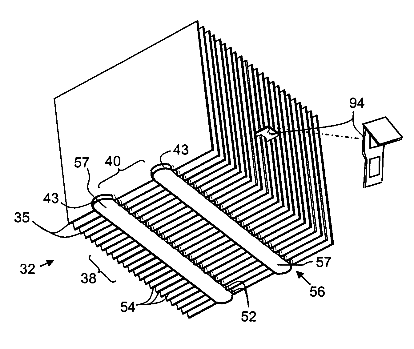
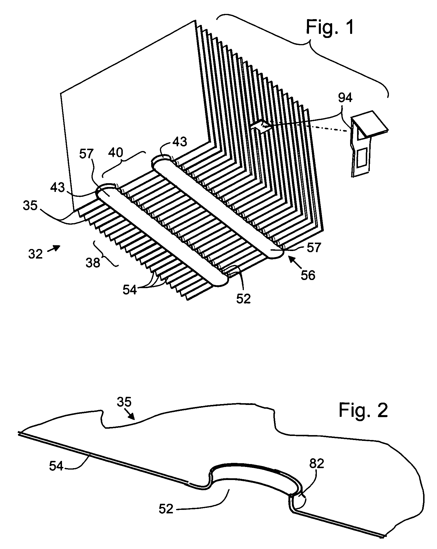
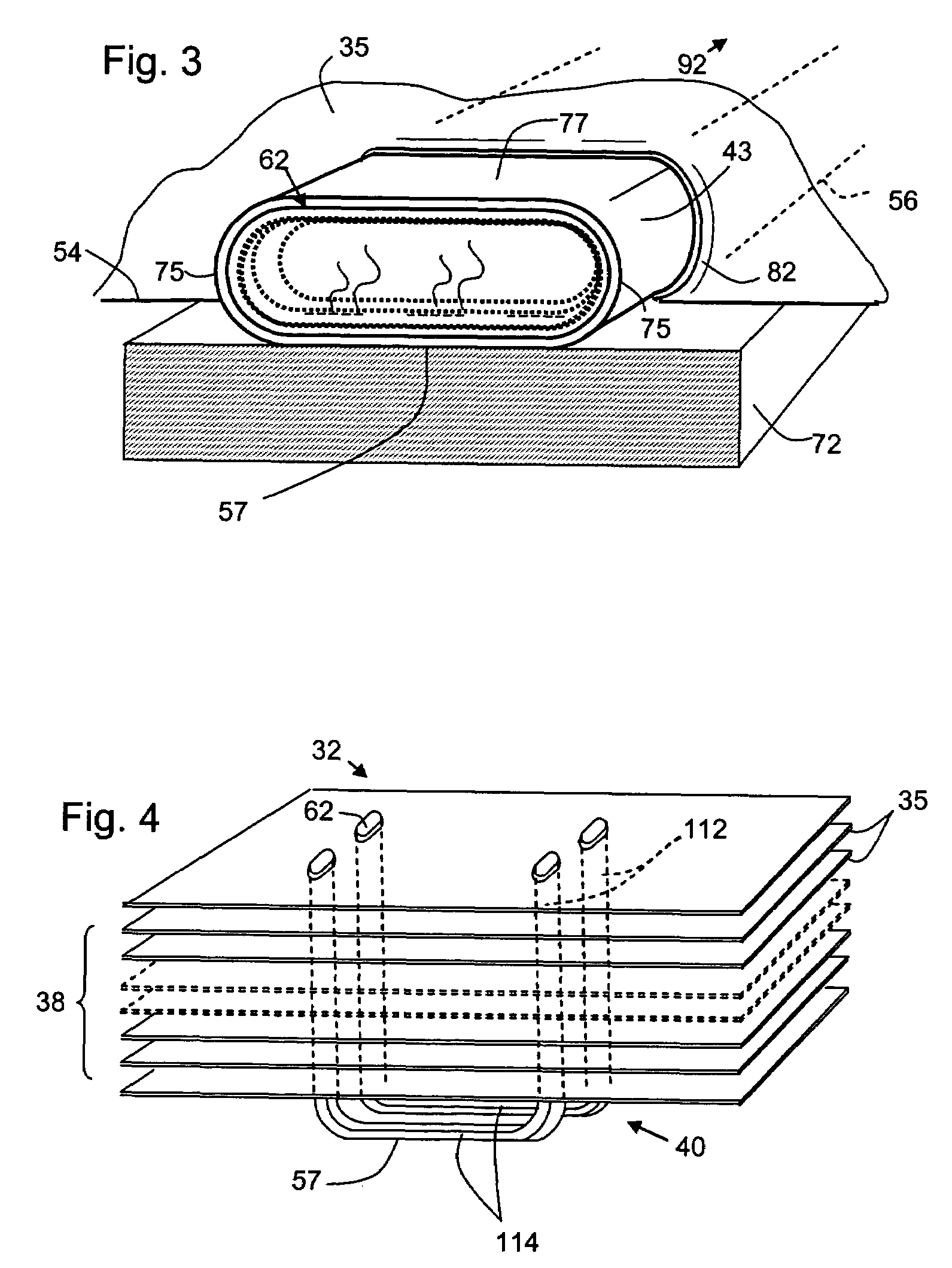
[0030]This description of preferred embodiments is to be read in connection with the accompanying drawings, together forming the description of the invention and illustrating certain non-limiting examples. The drawing figures are not necessarily to scale and represent some features in schematic form, in the interest of clarity and conciseness.

[0031]The invention provides a heat transfer device 32 for dissipating heat developed by a source such as an integrated circuit package. The device takes up heat energy by conduction with the source, and dissipates the heat by convection and radiant cooling, into the surrounding air. It is an aspect of the invention that the thermal energy pathways are as direct as practicable, and the structure of the device is substantially limited to those elements that are directly related to engaging the heat transfer device with the source and to dissipating the heat that the device collects.

[0032]An exemplary embodiment of the heat transfer device is sho...


PUM

PropertyMeasurementUnit
Shapeaaaaaaaaaa
Widthaaaaaaaaaa
Energyaaaaaaaaaa

Abstract

A heat sink for integrated circuits is limited substantially to heat transfer fins on one or more heat pipe tubes, the tube(s) functioning as a base for the heat sink. The heat pipe tube has a flattened oval cross-section and can snap-fit in openings through the fins. The tube is exposed on one side of the heat sink for contact with the heat generating circuit. The fins can be flat or irregular and can have a collar engaging the heat pipe tube. In one example, the heat pipe runs perpendicular to vertical fins along the bottom of a standing fin stack. In another embodiment two U-shaped heat pipe tubes carry a layered stack, the bottom of the U-shapes being presented under the lowermost in the stack. A clamp urges the heat sink against the heat source.

Description

CROSS-REFERENCE TO RELATED APPLICATIONS[0001]This is a Continuation-in-part Application of U.S. application Ser. No. 10 / 413,601, filed on Apr. 14, 2003 now U.S. Pat. No. 6,717,813.FIELD OF THE INVENTION[0002]The invention relates to heat exchangers, and in particular to a unit for dissipation of heat from a processor or other integrated circuit. One or more heat pipe tubes for thermally conductive contact with the circuit package extend along an edge of an array of parallel air convection fins. The heat pipe tube(s) are tapered toward a plane of contact with the circuit package, preferably having a flattened oval cross-section. This maximizes contact surface area on the heat pipe tubes and also provides a shape that structurally engages and supports the parallel fins on the heat pipe tubes. A clamping fixture arranged in the array of fins provides another structural member and a point for application of force to urge the heat pipe tubes into conductive contact with the circuit packa...

Claims


Application Information

Patent Timeline
IPC IPC(8): B23P15/26B21D53/08H01L23/40H01L23/427
CPCH01L23/4093H01L23/427F28D15/0275H01L2924/0002Y10T29/49377Y10T29/49368Y10T29/49353Y10T29/49378Y10T29/49364H01L2924/00F28F1/32
Inventor GARNER, SCOTT
Owner THERMAL
Why Eureka
Try Eureka