

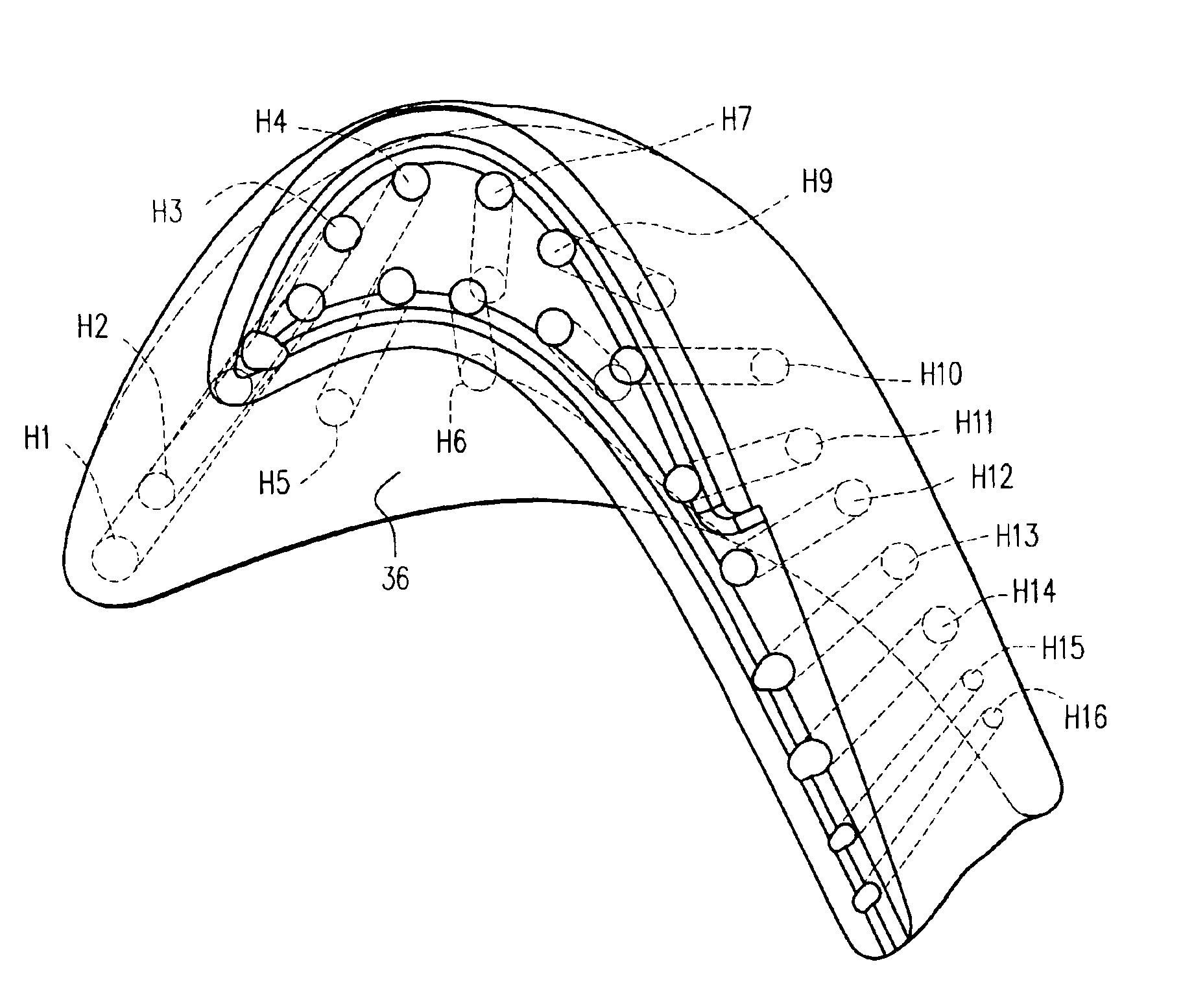
Perimeter-cooled turbine bucket airfoil cooling hole location, style and configuration
a technology of airfoil and bucket, which is applied in the direction of machines/engines, chemistry apparatuses and processes, and other chemical processes, can solve the problems of reducing affecting not cooling the bucket sufficiently, so as to increase the overall efficiency of the turbine, promote turbulence, and increase the air turbulence
- Summary
- Abstract
- Description
- Claims
- Application Information
AI Technical Summary
Benefits of technology
Problems solved by technology
Method used
Image

Examples
Embodiment Construction
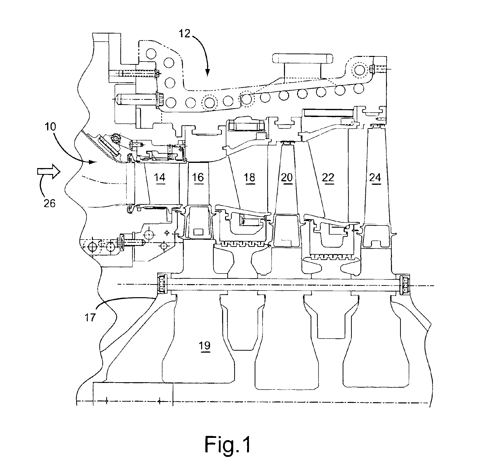
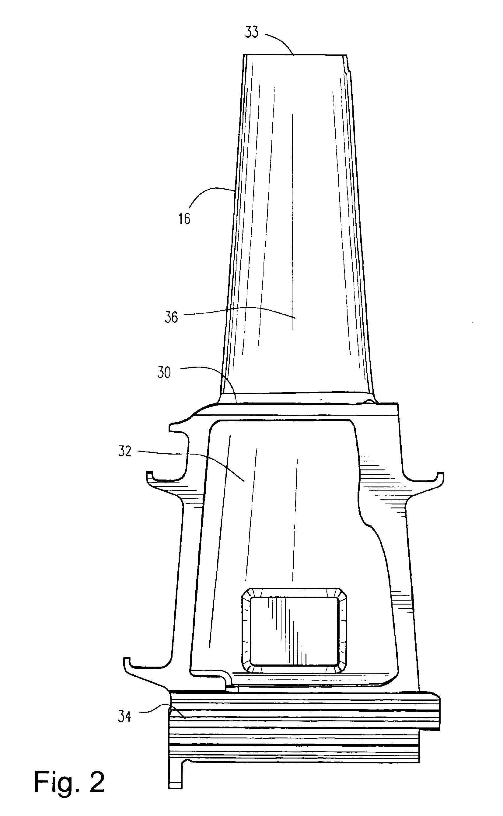
[0019]Referring now to the drawings, particularly to FIG. 1, there is illustrated a hot gas path, generally designated 10, of a gas turbine 12 including a plurality of turbine stages. Three stages are illustrated. For example, the first stage comprises a plurality of circumferentially spaced nozzles 14 and buckets 16. The nozzles are circumferentially spaced one from the other and fixed about the axis of the rotor. The first stage buckets 16, of course, are mounted on the turbine rotor 17. A second stage of the turbine 12 is also illustrated, including a plurality of circumferentially spaced nozzles 18 and a plurality of circumferentially spaced buckets 20 mounted on the rotor 17. The third stage is also illustrated including a plurality of circumferentially spaced nozzles 22 and buckets 24 mounted on rotor 17. It will be appreciated that the nozzles and buckets lie in the hot gas path 10 of the turbine, the direction of flow of the hot gas through the hot gas path 10 being indicate...
PUM
 Abstract
Description
Claims
Application Information