
Load bearing trundle

A technology of casters and rollers, applied in the field of transportation equipment, can solve the problems of difficult casters, high steering flexibility and load-bearing capacity, and achieve the effect of high steering flexibility

Inactive Publication Date: 2018-08-10
佛山市知而行信息科技有限公司
View PDF4 Cites 0 Cited by
  • Summary
  • Abstract
  • Description
  • Claims
  • Application Information

AI Technical Summary

Problems solved by technology

[0002] The casters installed under the mechanical equipment for moving and carrying equipment are long-term heavy weighted equipment. The flexibility of steering and the range of weighing have different emphases in different application environments. It is difficult to have a caster Can have high steering flexibility and load-bearing capacity at the same time

Method used


Image

  • Load bearing trundle

Examples


Embodiment Construction

[0014] The technical solutions of the present invention will be further described below in conjunction with the accompanying drawings and through specific implementation methods.

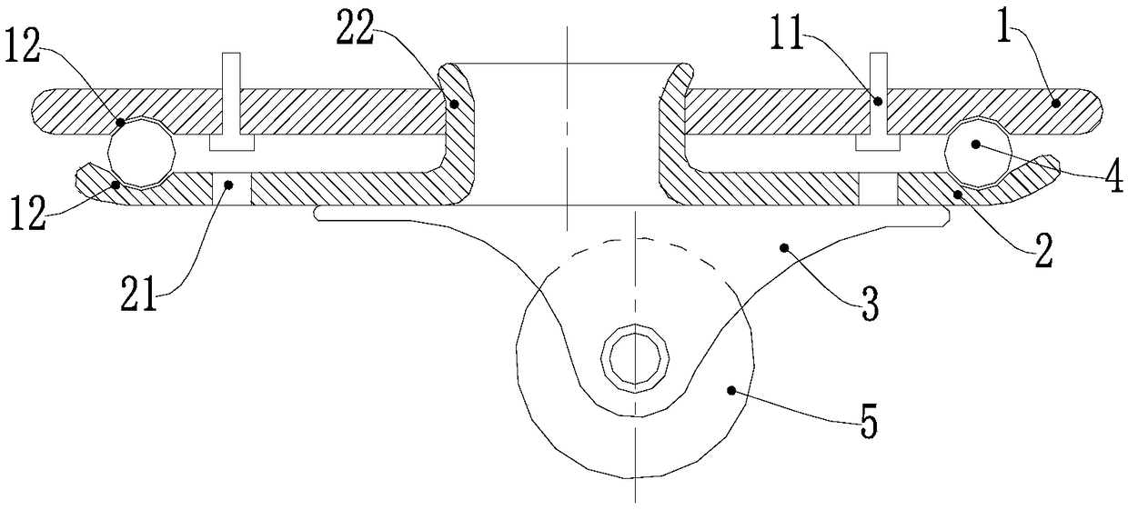
[0015] The load-bearing caster includes a base plate 1, a rotating plate 2, a riveting part 3, a ball 4 and a roller 5; the base plate 1 is provided with through holes for installing bolts 11, and the through holes are distributed in a circle, and the lower surface of the base plate 1 is connected to the The upper surface of the rotating plate 2 is provided with a circular groove 12 corresponding to the position, and the circular groove 12 is filled with balls 4. The balls 4 separate the bottom plate 1 and the rotating plate 2 from each other without direct contact. The gap between the plates 2 is enough to accommodate the nuts of the bolts 11; the central position of the bottom plate 1 is provided with a central through hole, and the central position of the rotating plate 2 is provided with a snap-i...


PUM


Abstract

A load bearing trundle comprises a bottom board, a rotary board, a riveting piece, balls and an idler wheel. Through holes used for installing bolts are formed in the bottom board and circumferentially distributed. Round grooves in the corresponding positions are formed in the lower surface of the bottom board and the upper surface of the rotary board and filled with the balls. The bottom board and the rotary board are separated from each other through the balls and do not make direct contact. A center through hole is formed in the center position of the bottom board, a clamping body is arranged in the center position of the rotary board, extends upwards into the center through hole and is clamped in the bottom board, and the bottom board and the rotary board form a rotatable hinging relationship. Avoidance holes used for the bolts to penetrate are formed in the rotary board. The riveting piece is riveted to the lower surface of the rotary board, extends downwards and is used for installing the idler wheel, and the idler wheel is installed on the riveting piece through an idler wheel shaft. Due to the change of the structure, force is borne more evenly, and therefore large weight can be borne.

Description

technical field [0001] The invention relates to the technical field of transportation equipment, in particular to load-bearing casters. Background technique [0002] The casters installed under the mechanical equipment for moving and carrying equipment are long-term heavy weighted equipment. The flexibility of steering and the range of weighing have different emphases in different application environments. It is difficult to have a caster It can have high steering flexibility and load-bearing capacity at the same time. Contents of the invention [0003] The purpose of the present invention is to provide a caster with outstanding steering flexibility and load-bearing capacity. [0004] For reaching this purpose, the present invention adopts following technical scheme: [0005] The load-bearing caster includes a base plate, a rotating plate, riveting parts, balls and rollers; the base plate is provided with through holes for installing bolts, and the through holes are dist...

Claims


Application Information

Patent Timeline
Patent Type & Authority Applications(China)
IPC IPC(8): B60B33/00
CPCB60B33/0005
Inventor 不公告发明人
Owner 佛山市知而行信息科技有限公司
Learn More