Test pattern creation method, test pattern, printing apparatus, and storage medium

A technology for testing patterns and manufacturing methods, applied to printing devices, devices for permanent visual display, printing, etc.

Active Publication Date: 2018-08-28
SEIKO EPSON CORP
View PDF9 Cites 6 Cited by
  • Summary
  • Abstract
  • Description
  • Claims
  • Application Information

AI Technical Summary

Problems solved by technology

[0003] The drop deviation of printing can also be caused by conditions other than the above two cases, so there is still room for improvement

Method used


Image

  • Test pattern creation method, test pattern, printing apparatus, and storage medium
  • Test pattern creation method, test pattern, printing apparatus, and storage medium
  • Test pattern creation method, test pattern, printing apparatus, and storage medium

Examples


Embodiment Construction

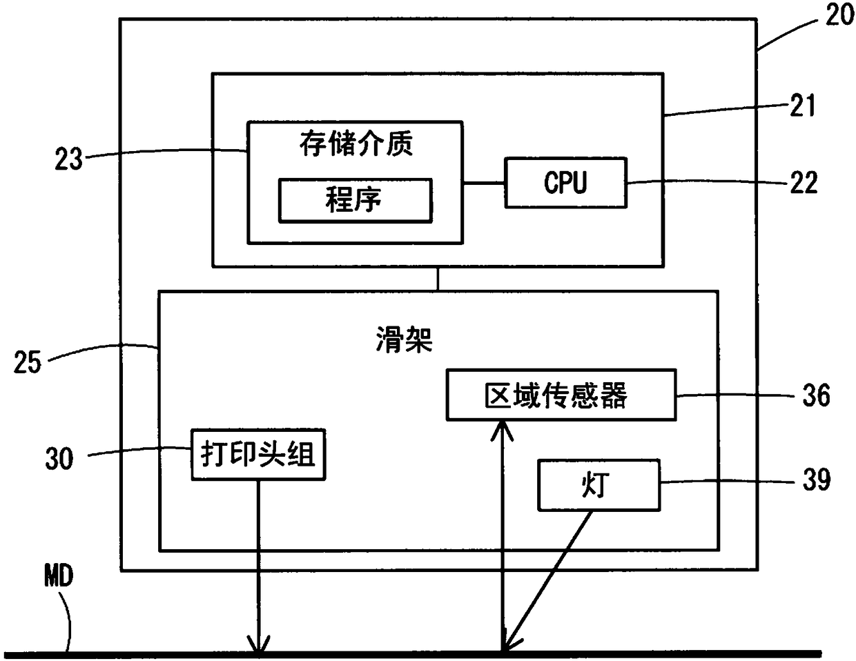
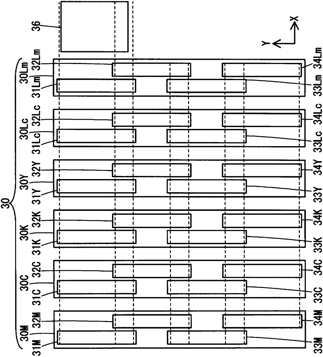
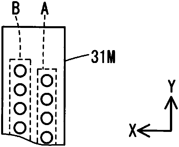
[0029] figure 1 is a functional block diagram of the printing device 20 . The printing device 20 includes a control unit 21 and a carriage 25 . The control unit 21 includes a CPU (Central Processing Unit, central processing unit) 22 and a storage medium 23 . The carriage 25 includes a head group 30 , an area sensor 36 and a lamp 39 .

[0030] The printing device 20 forms dots on the printing medium MD by ejecting ink onto the printing medium MD. The printing device 20 ejects six colors of ink. The 6 colors refer to CMYKLcLm, that is, cyan, magenta, yellow, black, light cyan, and light magenta. In order to form dots, the printing device 20 scans the carriage 25 in the main scanning direction and conveys the printing medium MD in the sub scanning direction. The main scanning direction intersects with the sub-scanning direction, more specifically, is orthogonal to the sub-scanning direction.

[0031] The area sensor 36 measures the brightness value on the printing medium MD...


PUM


Abstract

The invention provides a test pattern creation method for measuring the impact displacement of a new combination or at least three impact displacement, a test pattern, a printing apparatus and a storage medium. The test pattern creation method creates a test pattern through at least three modes in the parts for measurement of the impact displacement generated in the following conditions: a print head displacement between first and second print heads, chip displacement between first and second print chips, round-trip displacement between a forward pass and a reverse pass of main scanning, column displacement between first and second nozzle columns, position displacement of the first print head around a main scanning direction, and position displacement of the first print head, and an impactdisplacement due to position displacement of the first print head around a direction orthogonal to the main scanning direction and a direction intersecting with the main scanning direction. The testpattern has a length in a sub scanning direction less than that of the head. The at least three parts are arranged in the sub scanning direction.

Description

technical field [0001] The present disclosure relates to a printed test pattern. Background technique [0002] Patent Document 1 discloses a technique for detecting a deviation caused by the inclination of the recording head, or the forward and backward strokes of the recording head. The inclination referred to here refers to a positional deviation caused by a rotation centered on a direction perpendicular to the main scanning direction and the sub scanning direction. [0003] The drop deviation of printing may also occur due to circumstances other than the above two cases, so there is still room for improvement. In view of this, an object of the present disclosure is to create a test pattern capable of measuring a new combination of landing deviations or to create a test pattern capable of measuring at least three types of landing deviations. [0004] Patent Document 1: Japanese Unexamined Patent Publication No. 2007-15269. Contents of the invention [0005] One aspect...

Claims


Application Information

Patent Timeline
Patent Type & Authority Applications(China)
IPC IPC(8): B41J2/01B41J29/393G06K15/02
CPCB41J2/01B41J29/393G06K15/1807G06K15/1825G06K15/186B41J2029/3935B41J19/145B41J2/2135B41J2/04505B41J2/04586B41J2/155B41J2/2103B41J2/1433
Inventor 金井政史
Owner SEIKO EPSON CORP
Why Eureka
Try Eureka