Punching die mechanism

A die and support plate technology, applied in the die processing field, can solve the problems of die wear, frequent replacement, etc.

Pending Publication Date: 2018-09-04
苏州圣普亚精密制造有限公司
View PDF0 Cites 1 Cited by
  • Summary
  • Abstract
  • Description
  • Claims
  • Application Information

AI Technical Summary

Problems solved by technology

Since the stroke driven by the cylinder is a fixed distance, the pressing pressure is too large, resulting in relatively large mold wear and frequent replacement.

Method used


Image

  • Punching die mechanism
  • Punching die mechanism
  • Punching die mechanism

Examples


Embodiment

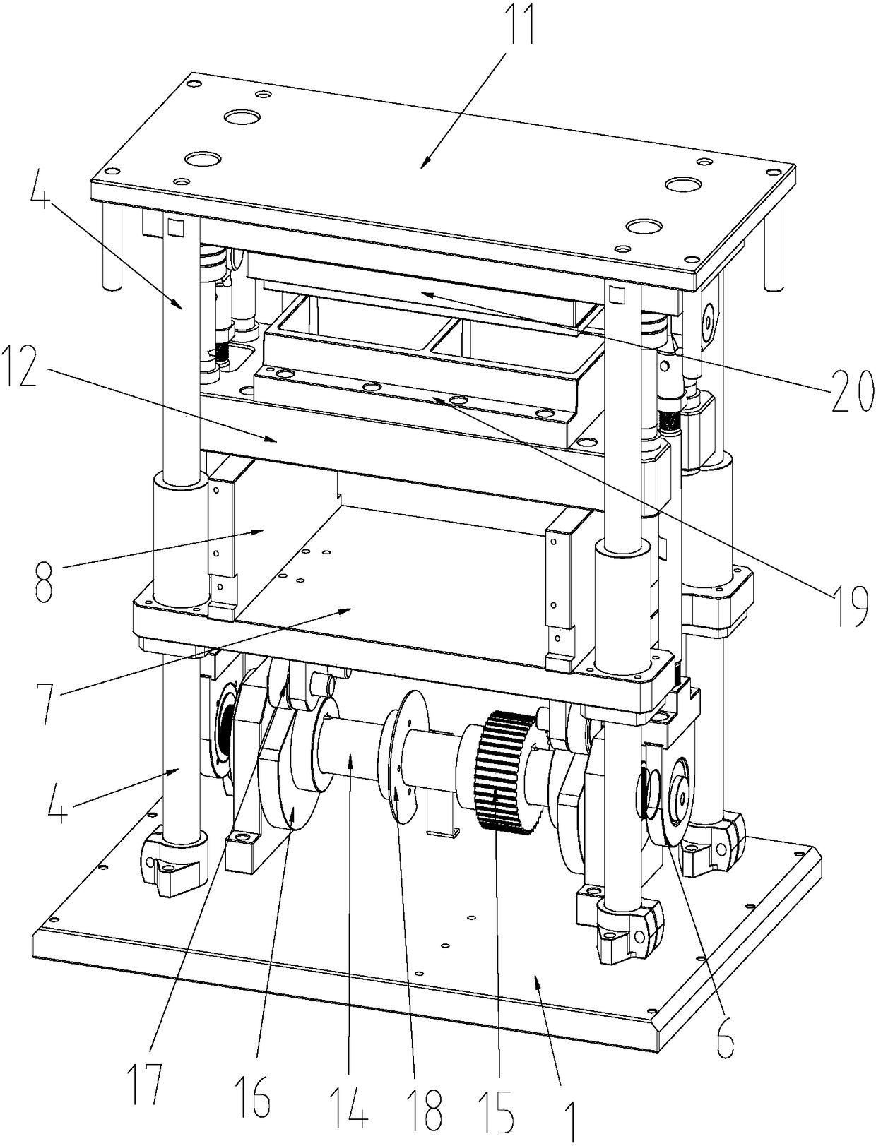
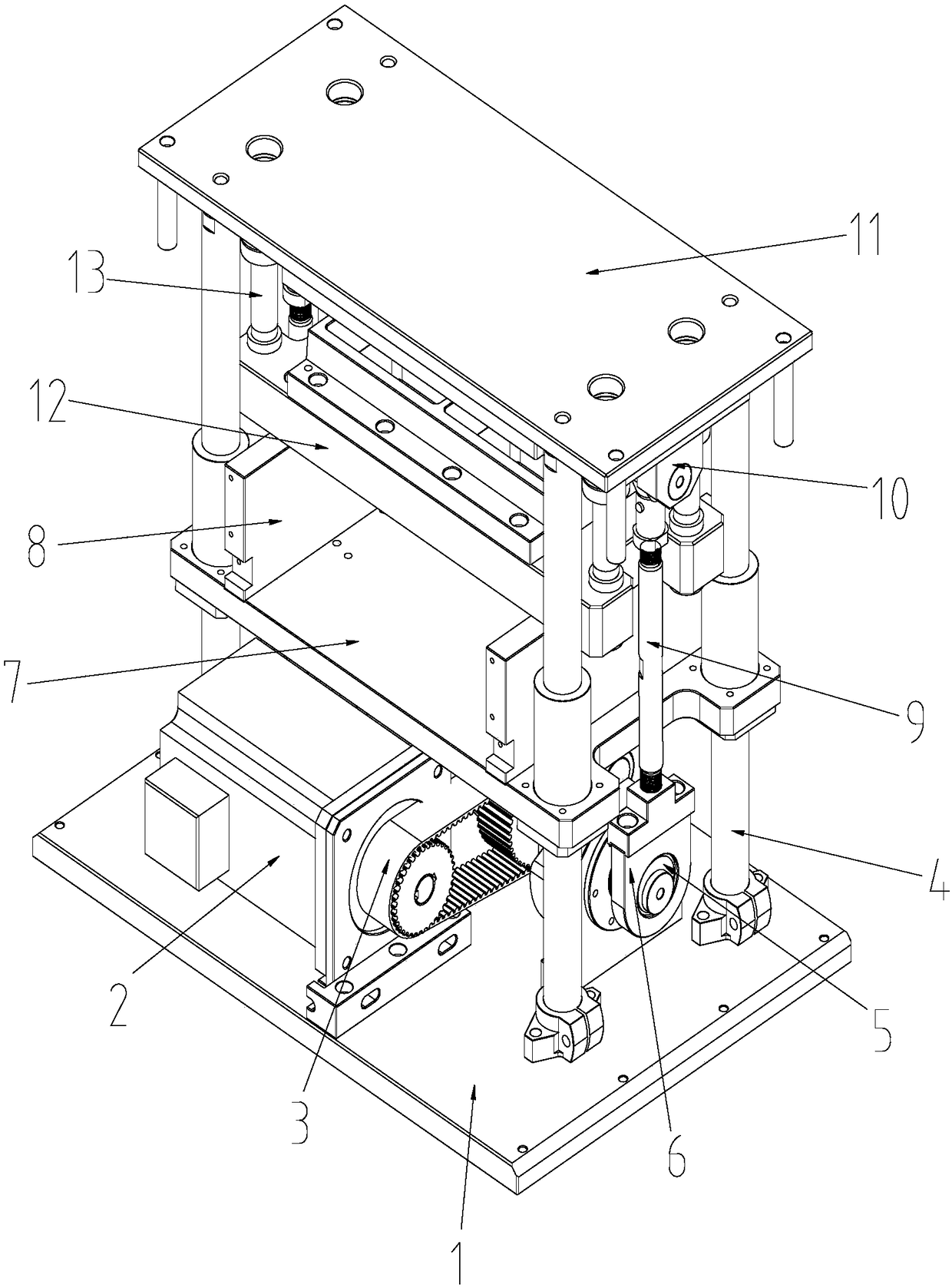
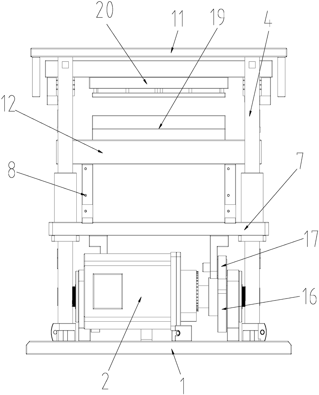
[0021] See attached Figure 1 to Figure 4 As shown, a die mechanism in this embodiment includes a mechanism bottom plate 1 and a mechanism top plate 11 distributed up and down, and a long guide column 4 is arranged between the mechanism top plate 11 and the mechanism bottom plate 1. The number of the above-mentioned long guide columns 4 There are four, distributed at the four corners of the mechanism bottom plate 1 and the mechanism top plate 11 (in this embodiment, the mechanism bottom plate 1 and the mechanism top plate 11 are both square structures). The long guide post 4 is provided with a guide post cover A, and the guide post cover A is connected to the die support base plate 7, and the die support base plate 7 is located between the mechanism base plate 1 and the mechanism top plate 11. The lower end surface of the mechanism top plate 11 is provided with contour columns, and the above-mentioned contour columns are arranged at four corners of the mechanism top plate 11 ....


PUM


Abstract

The invention discloses a punching die mechanism. The punching die mechanism comprises a mechanism bottom plate and a mechanism top plate; long guide columns are arranged between the mechanism top plate and the mechanism bottom plate, a punching die supporting bottom plate is arranged between the mechanism top plate and the mechanism bottom plate, and an upper punching die supporting plate and a lower punching die supporting plate are distributed on the punching die supporting bottom plate; a cam shaft and a driving motor which are connected with each other in a drive mode are located below the punching die supporting bottom plate, and the two sides of the cam shaft are fixed on the mechanism bottom plate through bearing seats A; and a cam block is arranged on the cam shaft, eccentric bearings are arranged at the two ends of the cam block, a rolling wheel assembly matched with the cam block is arranged on the lower end surface of the punching die supporting bottom plate, and the eccentric bearings are connected to the upper punching die supporting plate through a connecting rod mechanism. According to the punching die mechanism, the eccentric bearings and the cam block are driven to rotate through one driving motor, the relative operation between a lower punching die assembly and an upper punching die assembly is achieved through a corresponding connecting structure, so that the two-way punching operation is realized; and meanwhile, accurate positioning can be realized by adopting the driving motor, and the abrasion ratio of a die can be reduced.

Description

technical field [0001] The invention relates to the field of die processing, in particular to a die mechanism for driving a die plate to move upward by a driving motor. Background technique [0002] The traditional punching die mechanism adopts the method of fixing the lower die and pressing down the upper die to carry out the stamping operation. The driving element used is generally a press-down cylinder, which drives the press-down of the upper die to realize the stamping of the parts. Because the stroke driven by the cylinder is fixed distance, the pressing pressure is too large, resulting in relatively large mold wear and frequent replacement. Contents of the invention [0003] In order to overcome the above disadvantages, the object of the present invention is to provide a punching die mechanism, which adopts the form of a motor-driven cam to realize the punching operation of the die. [0004] In order to achieve the above object, the technical solution adopted by th...

Claims


Application Information

Patent Timeline
IPC IPC(8): B21D22/02B30B1/26
CPCB21D22/02B30B1/261B30B1/266
Inventor 李楠
Owner 苏州圣普亚精密制造有限公司
Why Eureka
Try Eureka