A high-precision high-speed punch

A high-speed punching and high-precision technology, applied in the field of machine tools, can solve problems such as large fluctuations in product size, unstable air pressure, and small punching force range, and achieve the effects of improving product processing efficiency, automation, and production efficiency

Active Publication Date: 2021-07-16
杭州临安华冠家具有限公司
View PDF7 Cites 0 Cited by
  • Summary
  • Abstract
  • Description
  • Claims
  • Application Information

AI Technical Summary

Problems solved by technology

[0002] Existing pneumatic structure punching machines use cylinders to stretch and push stamping products. The defects are: first, the air pressure is unstable, the consistency of each stamping effect is poor, the product size fluctuates greatly, and the product dimensional stability is poor; , the stamping force is determined by the air pressure, the range of stamping force that can be provided is small, and the applicable product types are narrow
However, each reciprocation of the upper die part can only complete one stamping, and the continuity of the punching machine's work is limited, which affects the stamping efficiency of the product

Method used


Image

  • A high-precision high-speed punch
  • A high-precision high-speed punch
  • A high-precision high-speed punch

Examples


Embodiment 1

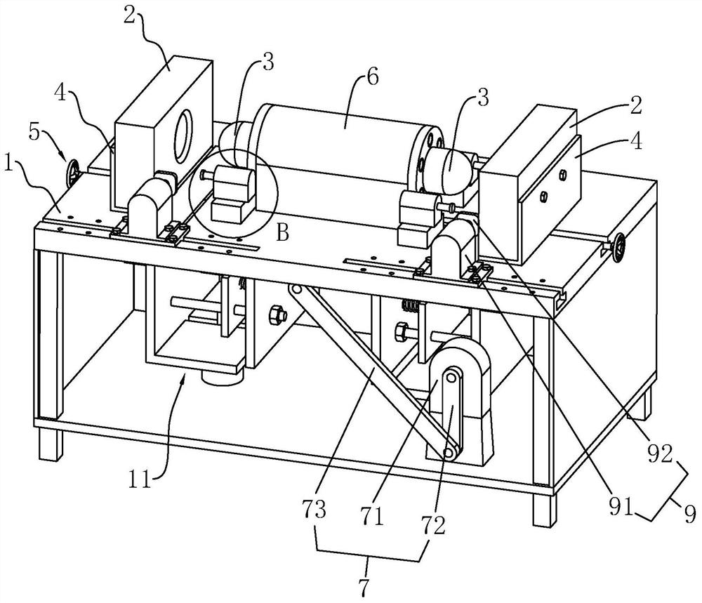
[0041] See figure 1 A high-precision high-speed punch, including a table 1, a stamped concave die 2 fixed to the table 1 and a sliding shift disposed on the table 1, and a table 1 is also provided with a driving stamping The convex mold 3 is a drive mechanism 7 that linearly reciprocates. In the actual work, the workpiece is placed at the stamping die 2, the drive mechanism 7 drives the punching convex mold 3 away from or near the stamped concave die 2; during this process, the punching convex mold 3 impacts the workpiece, thereby completing the workpiece together with the stamped die 2 Stamping.

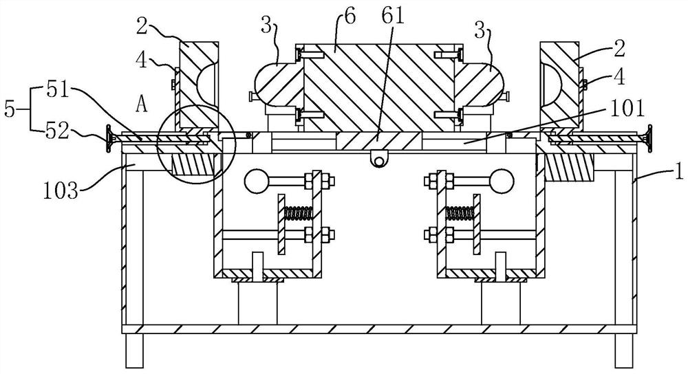
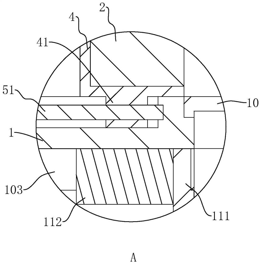
[0042] See figure 1 The above stamping fixtures 2 are symmetrically disposed in the working table 1 longitudinal direction. In order to install the two stamping recess 2, two sets of fixed seats 4 for fixing the two stamping die 2 are provided on the table 1, and the two stamped concave die 2 can be disassembled to the corresponding fixing seat 4, respectively, respectively. One side of...

Embodiment 2

[0057] See Figure 7 A high-precision high speed punch, which is different from that of Example 1, and the two stamped concave molds 2 are first stamped concave die 21 and the second stamping die 22, and the first stamped die 21 and the second.The stamping die 22 corresponds to two different stamped structures, that is, the mold forming side structure of the two is not the same.Correspondingly, the two stamping convex molds 3 are respectively used for the first stamping convex mold 31, respectively, and the first stamped convex mold 31 and the second stamping convex mold 32 are respectively used to cooperate with the first stamping die 21 and the first.Two stamping die 22.As such, the punch can be completed simultaneously to complete two forms of stamping, which helps further improve processing efficiency.


PUM


Abstract

The invention discloses a high-precision high-speed punching machine, which relates to the technical field of machine tools, and includes a workbench, a stamping die fixedly arranged on the workbench, a stamping punch movably arranged on the workbench, and a drive for driving the punching die There are two sets of stamping dies symmetrically arranged on the workbench, and the side adjacent to the two stamping dies is the mold forming side; a sliding seat connected to the driving mechanism is provided between the two stamping dies, and the sliding seat is along the two stamping dies. The connection direction of the concave die is horizontally slidable and arranged on the workbench; a punching punch is fixed on both sides of the sliding seat in the sliding direction, and the two punching punches correspond to the two punching dies one by one. The invention provides a high-precision high-speed punching machine with stable work, high degree of automation, convenient operation, continuous punching of two identical or different workpieces, and greatly improved production efficiency.

Description

Technical field [0001] The present invention relates to the field of machine tools, and more particularly to a high-precision high speed punch. Background technique [0002] The existing pneumatic structural punch is used to promote the stamping product. It is defective in which the air pressure is unstable. The consistency of the stamping effect is poor. The product size is much fluctuation, the product size is poor; its second, cylinder stamping The punching force is determined by the air pressure, and the range value of the rushing force can be provided is small, and the product type is narrow. [0003] For the above problems, a practical novel patent of CN207931134U is disclosed, and a stamped small electric punch is disclosed, including a stamping portion, a lower die, a eccentric wheel motion mechanism, a motor drive unit, a table, and a substrate, and the stamping portion comprises The mold unit, the floating portion, and the guide portion, the upper mold seat and the floa...

Claims


Application Information

Patent Timeline
Patent Type & Authority Patents(China)
IPC IPC(8): B21D22/02B21D43/00B21D43/02B21D45/02B21D43/20
CPCB21D22/02B21D43/003B21D43/02B21D43/20B21D45/02
Inventor 朱炳华
Owner 杭州临安华冠家具有限公司
Why Eureka
Try Eureka