Seal ring forming process

A molding process and sealing ring technology, applied in the field of hardware processing, can solve the problems of affecting the stamping progress, waste of rubber sheets, inconvenient access to sealing rings, etc., and achieve the effect of saving rubber sheets and continuous stamping.

Active Publication Date: 2020-07-14
常州定远塑胶制品有限公司
View PDF15 Cites 0 Cited by
  • Summary
  • Abstract
  • Description
  • Claims
  • Application Information

AI Technical Summary

Problems solved by technology

[0003] In order to realize the continuous stamping of the sealing ring, usually a large piece of rubber plate is placed on the conveyor belt for stamping during the transmission process, so as to obtain multiple sealing rings; but the conveyor belt is also running during the movement of the first mold, this The time difference will cause the rubber sheet to be wasted during the second stamping
If the conveyor belt is stopped every time punching, on the one hand, the rubber sheet will slide forward under inertia, which will also lead to waste of rubber sheet, and on the other hand, it will also affect the punching progress when the driving mechanism is easy to be damaged
At the same time, due to the annular structure of the sealing ring, the rubber sheet of the hollow part of the sealing ring will inevitably be discarded after stamping, which will also cause waste of the rubber sheet. Moreover, the sealing ring after stamping is inconvenient to take, which also affects the continuous processing of the sealing ring a reason for

Method used


Image

  • Seal ring forming process
  • Seal ring forming process
  • Seal ring forming process

Examples


Embodiment Construction

[0021] Further detailed explanation through specific implementation mode below:

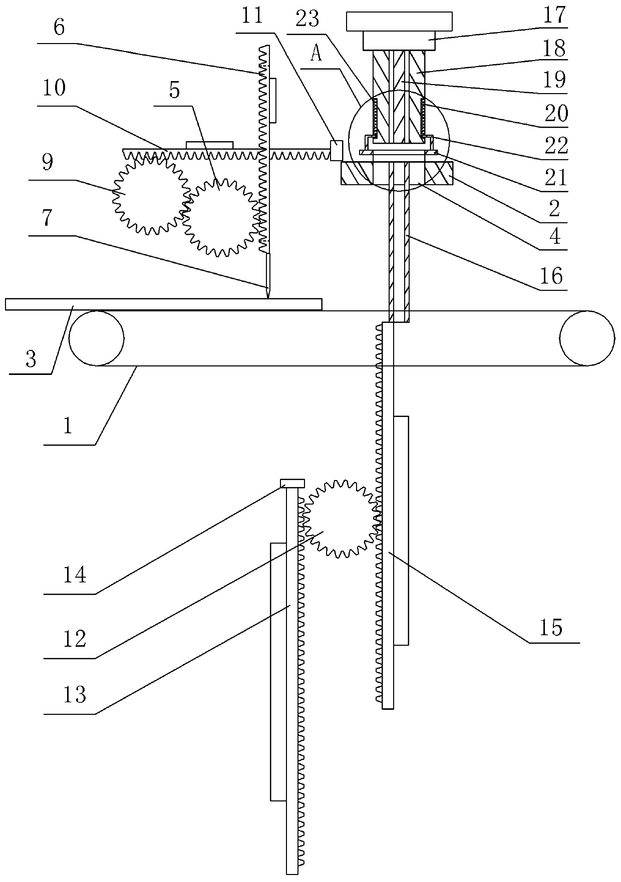
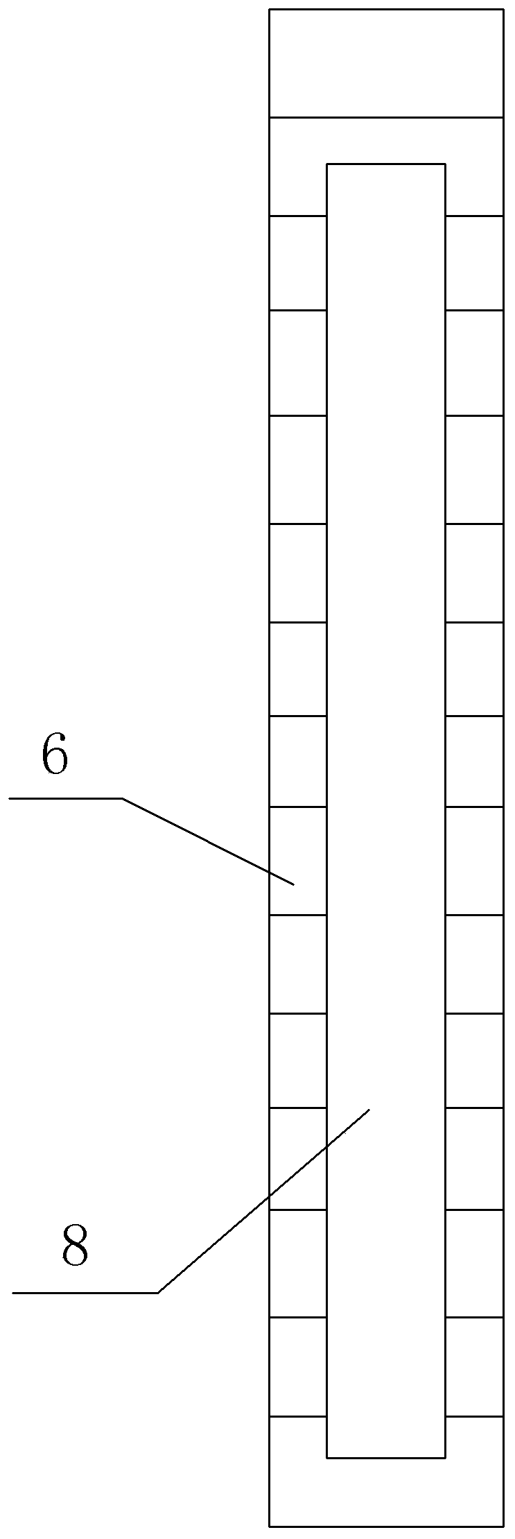
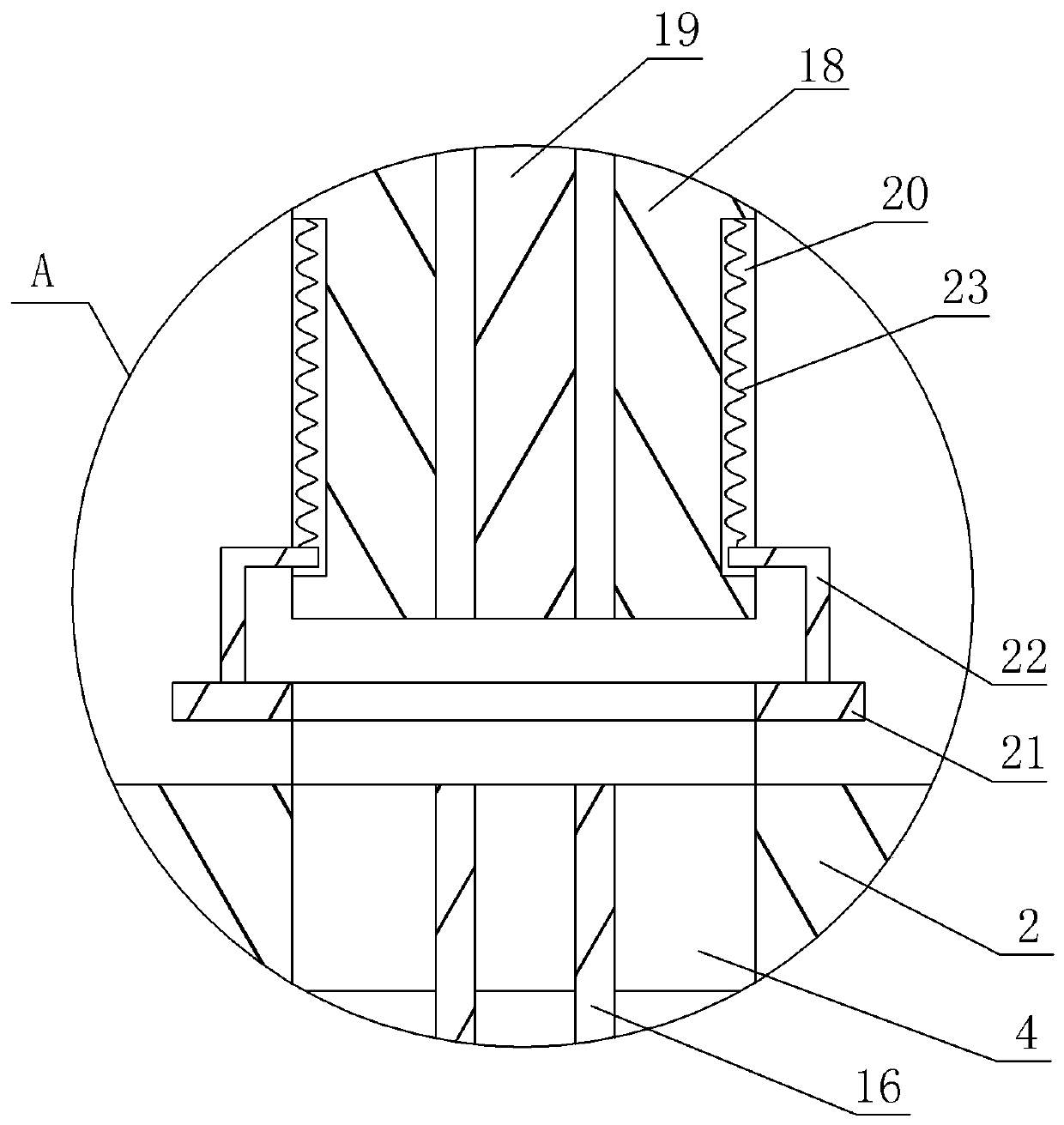
[0022] The reference signs in the drawings of the description include: the first conveyor belt 1, the stamping table 2, the rubber plate 3, the through hole 4, the first gear 5, the first rack 6, the cutting knife 7, the channel 8, the second gear 9, Second rack 10, push block 11, third gear 12, third rack 13, transfer block 14, fourth rack 15, auxiliary stamping tube 16, punch 17, annular stamping tube 18, auxiliary stamping rod 19 , Groove 20, positioning block 21, support rod 22, spring 23.

[0023] The sealing ring molding process specifically includes the following steps:

[0024] Step 1: Prepare a figure 1 The sealing ring stamping device shown includes a transfer mechanism, a first conveyor belt 1, a second conveyor belt, a cutting and pushing mechanism, a stamping table 2 and a stamping mechanism from bottom to top. The first conveyor belt 1 and the second conveyor belt are arranged si...


PUM


Abstract

The invention relates to the field of hardware machining, in particular to a seal ring forming process. The seal ring forming process comprises the following steps that 1, a seal ring punching deviceis prepared; 2, a cutting unit and a third rack are moved to a conveying belt; 3, a pushing unit pushes a cut rubber plate to move to a punching table; 4, an annular punching pipe, an auxiliary punching rod and an auxiliary punching pipe are moved to the punching table; 5, the rubber plate is positioned through a positioning unit, the annular punching pipe is matched with the punching table to punch a seal ring with large size, and the auxiliary punching rod is matched with the auxiliary punching pipe to punch a seal ring with small size; and 6, the seal ring with the small size and the seal ring with the large size are collected in a separated manner. By means of the technical scheme, the rubber plate can be saved, and seal ring continuous machining is achieved.

Description

technical field [0001] The invention relates to the field of hardware processing, in particular to a sealing ring forming process. Background technique [0002] As a sealing component, the sealing ring is widely used in various equipment and components, and consumes a lot in components such as flanges. A typical sealing ring processing equipment is a punch press, which includes a power mechanism, which is usually provided by an external power source, and the power mechanism drives the first mold to move up and down, and the second mold is fixed at an appropriate position on the punch press, and the first mold and The opposite surfaces of the second mold have matching shapes, so that the first mold and the second mold can squeeze each other to obtain a sealing ring of expected specification and shape when the punch press is working. During the processing of the sealing ring, it is first necessary to turn on the power and start the punching machine. The power mechanism drives...

Claims


Application Information

Patent Timeline
Patent Type & Authority Patents(China)
IPC IPC(8): B26D9/00B26D1/08B26D5/08B26D7/06B26F1/40
CPCB26D1/085B26D5/083B26D7/0608B26D7/0625B26D9/00B26F1/40
Inventor 许根海
Owner 常州定远塑胶制品有限公司
Why Eureka
Try Eureka