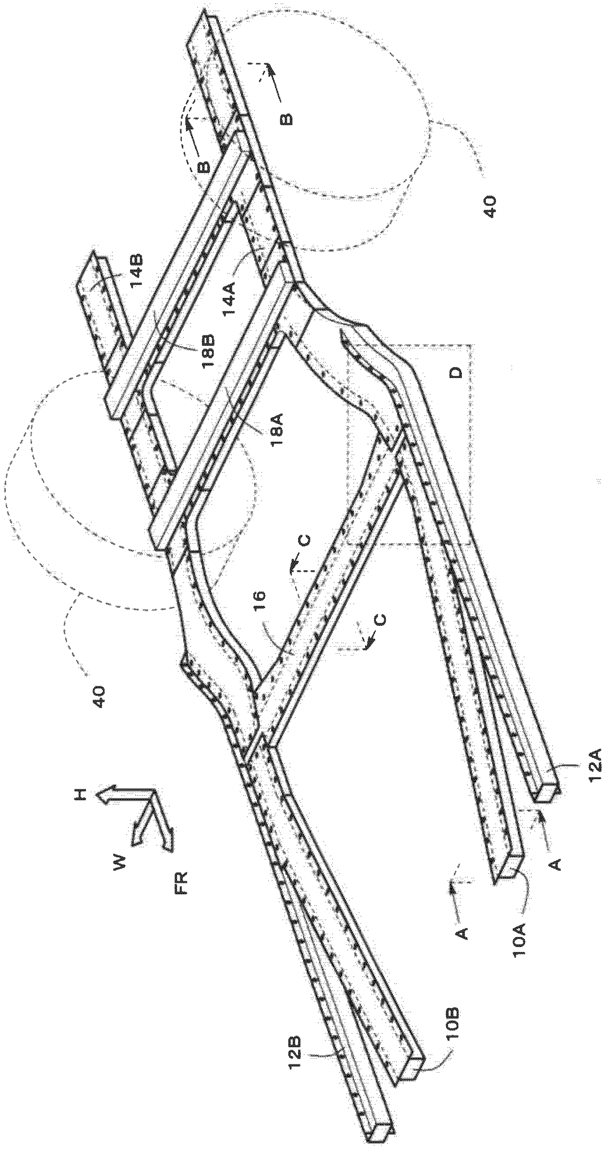
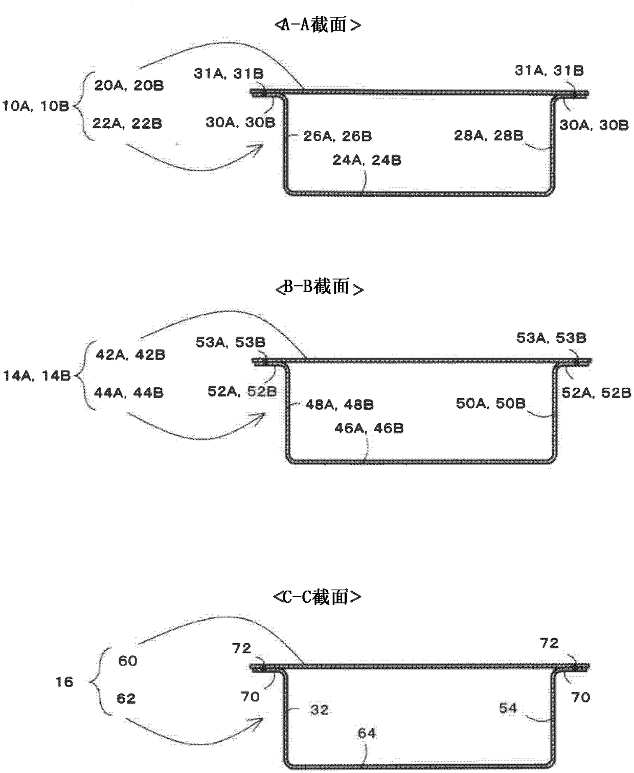
Vehicle rear structure
A technology for the rear and structure of a vehicle, which is applied in the direction of vehicle components, substructure, and superstructure to achieve the effect of restraining inclination
- Summary
- Abstract
- Description
- Claims
- Application Information
AI Technical Summary
Problems solved by technology
Method used
Image
Examples
Embodiment approach
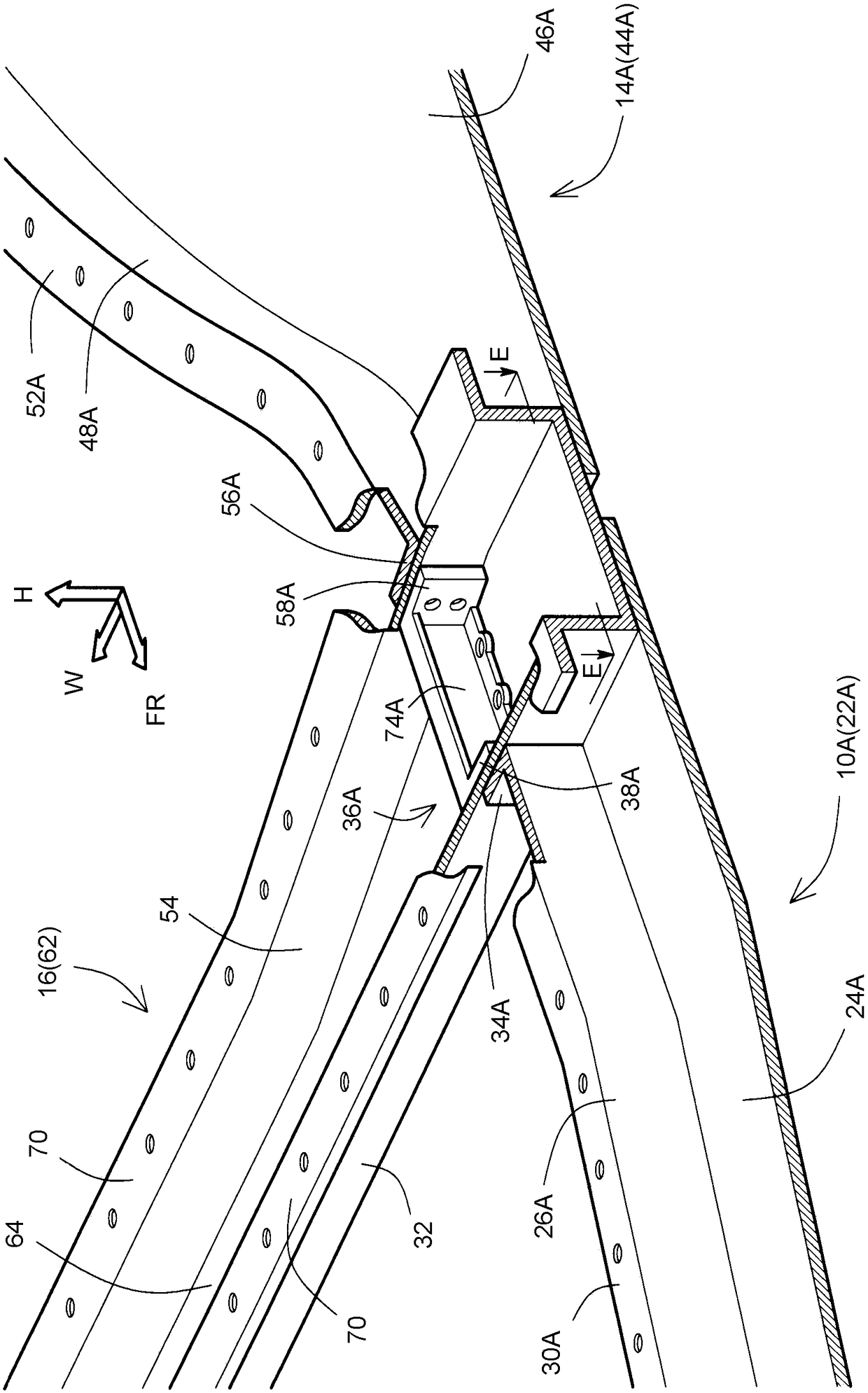
[0079] In the above-described embodiment, the side walls 74A, 74B and the facing flanges 38A, 38B of the reinforcement members 36A, 36B are formed into the outer hook shape, and the side walls 26A, 26B of the bottom reinforcement members 10A, 10B and the side wall flange 34A , 34B are made into an inner hook shape, but it is not limited to this form.
[0080] For example Figure 7 As shown, the side walls 74A, 74B and the opposite flanges 38A, 38B of the reinforcement members 36A, 36B and the side walls 26A, 26B and the side wall flanges 34A, 34B of the bottom reinforcement members 10A, 10B can also be set as outer hooks. shape.
[0081] In addition, side walls 74A, 74B (third side walls) of reinforcement members 36A, 36B and side walls 26A, 26B (fifth side walls) of floor reinforcement 10A, 10B may overlap in the vehicle width direction. Thereby, a load (compressive load) can be transmitted from the side walls 74A, 74B of the reinforcement members 36A, 36B to the side walls...
PUM
 Abstract
Description
Claims
Application Information
 - R&D
- Intellectual Property
- Life Sciences
- Materials
- Tech Scout
- Unparalleled Data Quality
- Higher Quality Content
- 60% Fewer Hallucinations
Browse by: Latest US Patents, China's latest patents, Technical Efficacy Thesaurus, Application Domain, Technology Topic, Popular Technical Reports.
© 2025 PatSnap. All rights reserved.Legal|Privacy policy|Modern Slavery Act Transparency Statement|Sitemap|About US| Contact US: help@patsnap.com


