Vehicle rear structure

A technology for the rear and structure of a vehicle, which is applied in the directions of vehicle components, substructure, and superstructure to achieve the effect of restraining inclination

Active Publication Date: 2020-08-11
TOYOTA JIDOSHA KK
View PDF6 Cites 0 Cited by
  • Summary
  • Abstract
  • Description
  • Claims
  • Application Information

AI Technical Summary

Problems solved by technology

Load input from the rear of the vehicle to the rear side member 100 due to a rear collision

Method used


Image

  • Vehicle rear structure
  • Vehicle rear structure
  • Vehicle rear structure

Examples


Embodiment approach

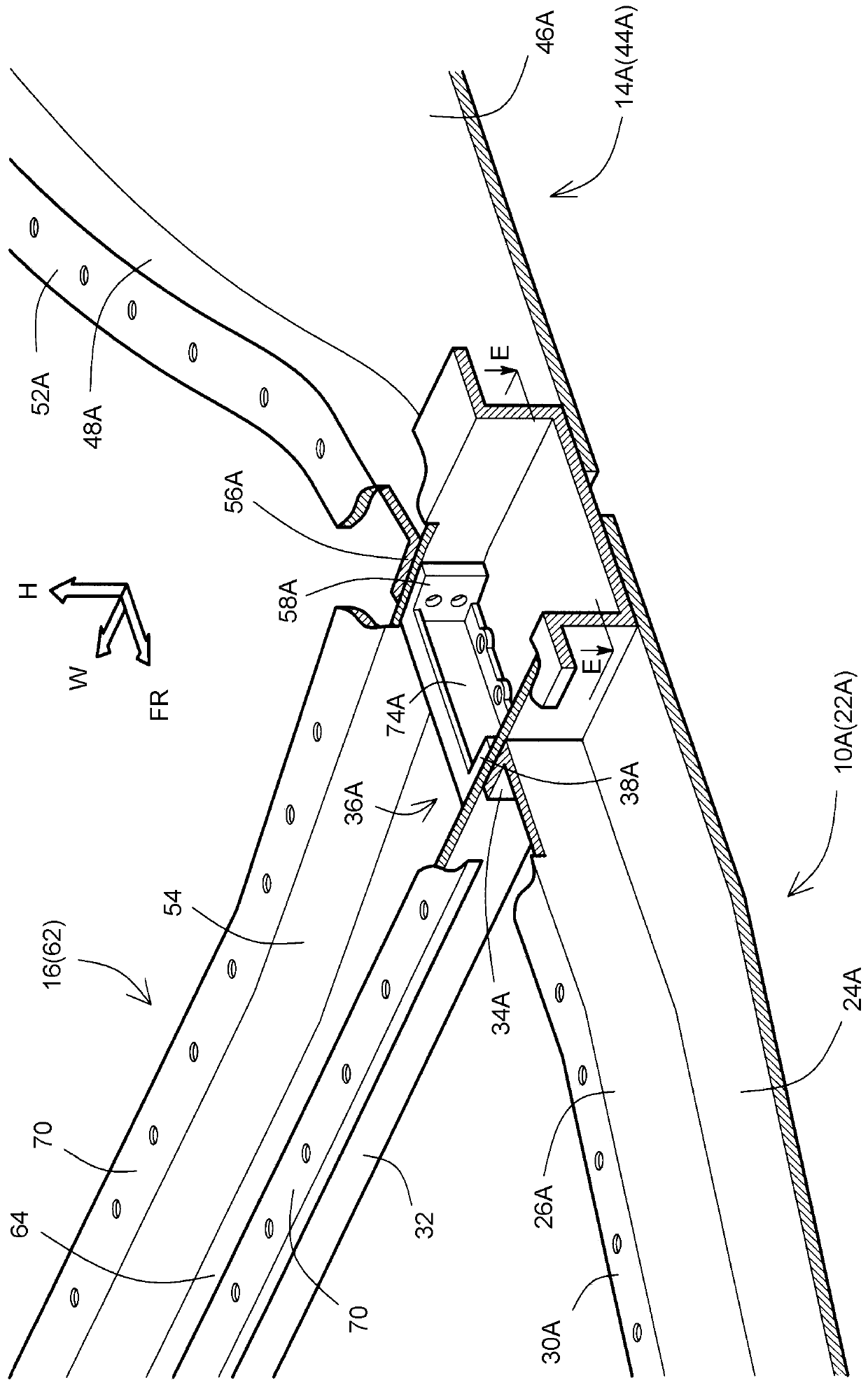
[0079] In the above-described embodiment, the side walls 74A, 74B and the facing flanges 38A, 38B of the reinforcement members 36A, 36B are formed into the outer hook shape, and the side walls 26A, 26B of the bottom reinforcement members 10A, 10B and the side wall flange 34A , 34B are made into an inner hook shape, but it is not limited to this form.

[0080] For example Figure 7 As shown, the side walls 74A, 74B and the opposite flanges 38A, 38B of the reinforcement members 36A, 36B and the side walls 26A, 26B and the side wall flanges 34A, 34B of the bottom reinforcement members 10A, 10B can also be set as outer hooks. shape.

[0081] In addition, side walls 74A, 74B (third side walls) of reinforcement members 36A, 36B and side walls 26A, 26B (fifth side walls) of floor reinforcement 10A, 10B may overlap in the vehicle width direction. Thereby, a load (compressive load) can be transmitted from the side walls 74A, 74B of the reinforcement members 36A, 36B to the side walls...


PUM


Abstract

The invention provides a vehicle rear structure. The rear side member has a side wall inclined outward in the vehicle width direction away from the rear wheels of the vehicle, and a side wall flange bent from the front end of the side wall to extend inward in the vehicle width direction. The center floor cross member has side walls that abut the side wall flanges of the rear rails. The reinforcing member includes a side wall extending to the side wall of the center floor cross member, and a flange bent from the rear end of the side wall and extending outward in the vehicle width direction, at least part of the flange interposing the center floor cross member. The side wall of the side wall coincides with the side wall flange of the rear side member in the vehicle width direction.

Description

technical field [0001] The present invention relates to vehicle rear construction, and more particularly to the construction of skeletal components for the rear of a vehicle. Background technique [0002] Figure 10 An example is shown of a plan view of a part of a frame member that maintains the strength of the vehicle in the underbody of the vehicle. in particular, Figure 10 The frame members shown are arranged from the center portion in the traveling direction of the vehicle toward the rear periphery, and include a rear side member 100 , a center floor cross member 102 , and a floor reinforcement 104 . In addition, in Figure 10 In FIG. 2 , for the sake of simplicity, a rocker arm (also referred to as a side sill) provided in parallel with the bottom reinforcement 104 at an end in the vehicle width direction is not shown. [0003] The rear side member 100 extends in the front-rear direction of the vehicle (the FR direction in the drawing), and the flange 108 at the fron...

Claims


Application Information

Patent Timeline
Patent Type & Authority Patents(China)
IPC IPC(8): B62D21/02B62D21/15
CPCB62D21/02B62D21/152B62D21/03B62D27/023B62D29/007
Inventor 吉本雅则北川和弘
Owner TOYOTA JIDOSHA KK
Why Eureka
Try Eureka