
Optical fiber transmission device and method for USB (Universal Serial Bus) interface

A USB interface and optical fiber transmission technology, applied in the field of optical fiber transmission, can solve the problems of different signal characteristics of USB3.0 and USB2.0, high power consumption and cost, and many devices used.

Active Publication Date: 2018-09-28
NANJING QINHENG MICROELECTRONICS CO LTD
View PDF6 Cites 0 Cited by
  • Summary
  • Abstract
  • Description
  • Claims
  • Application Information

AI Technical Summary

Problems solved by technology

[0002] In the prior art, using optical fiber to transmit the signal of the USB 3.0 interface will encounter two problems: 1. The existing USB 3.0 is compatible with the signal of USB 2.0, and the characteristics of the signal of USB 3.0 and USB 2.0 are different. Therefore, when using USB 3.0 interface for signal transmission, each need to use a pair of optical fibers to transmit data of USB 2.0 and USB3.0 / 3.1 specifications
This transmission method will increase the number of photoelectric transceiver devices, increase system power consumption and cost, and is not convenient for users to use
2. The physical signal of USB2.0 data cannot be transmitted directly through optical fiber, and generally needs to be transmitted through optical fiber after converting the format
However, the technical solution disclosed by CN104101965B has the following technical problems: on the one hand, after the USB2.0 signal is converted into a USB3.0 signal, the original USB3.0 transmission channel is shared with the USB3.0 signal, occupying the original USB3.0 bandwidth, and the USB3.0 signal cannot be realized. .0 full bandwidth transmission; on the other hand, the overall solution uses more devices, and the power consumption and cost are higher

Method used


Image

  • Optical fiber transmission device and method for USB (Universal Serial Bus) interface
  • Optical fiber transmission device and method for USB (Universal Serial Bus) interface

Examples


Embodiment Construction

[0019] The present invention will be described in detail below in conjunction with the accompanying drawings and specific embodiments.

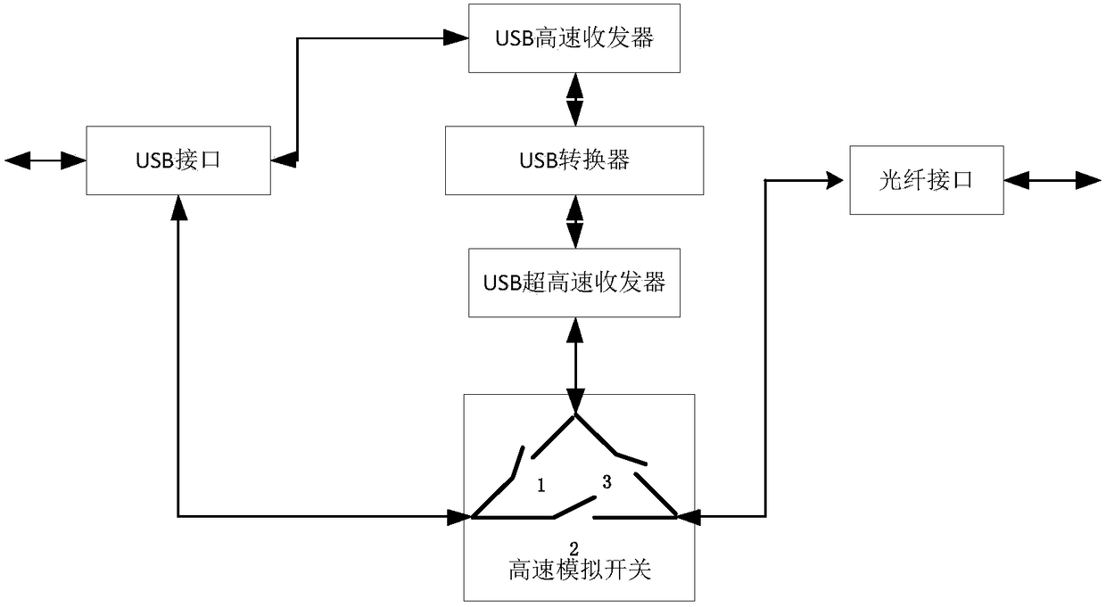
[0020] figure 1 It is a structural diagram of an optical fiber transmission device for a USB interface, the device includes a USB interface and an optical fiber interface, and also includes a USB high-speed transceiver (HS, HighSpeed), the USB high-speed transceiver is connected to the USB interface, and the USB The high-speed transceiver is connected with the USB converter, and the USB converter is connected with the USB super high-speed transceiver, and the USB super high-speed transceiver is connected with the first interface of the high-speed analog switch, and the second interface of the high-speed analog switch and the third interface are respectively connected with the USB interface and the optical fiber interface; the USB high-speed transceiver is used to send and receive USB high-speed or low full-speed data on the one hand; on the o...


PUM


Abstract

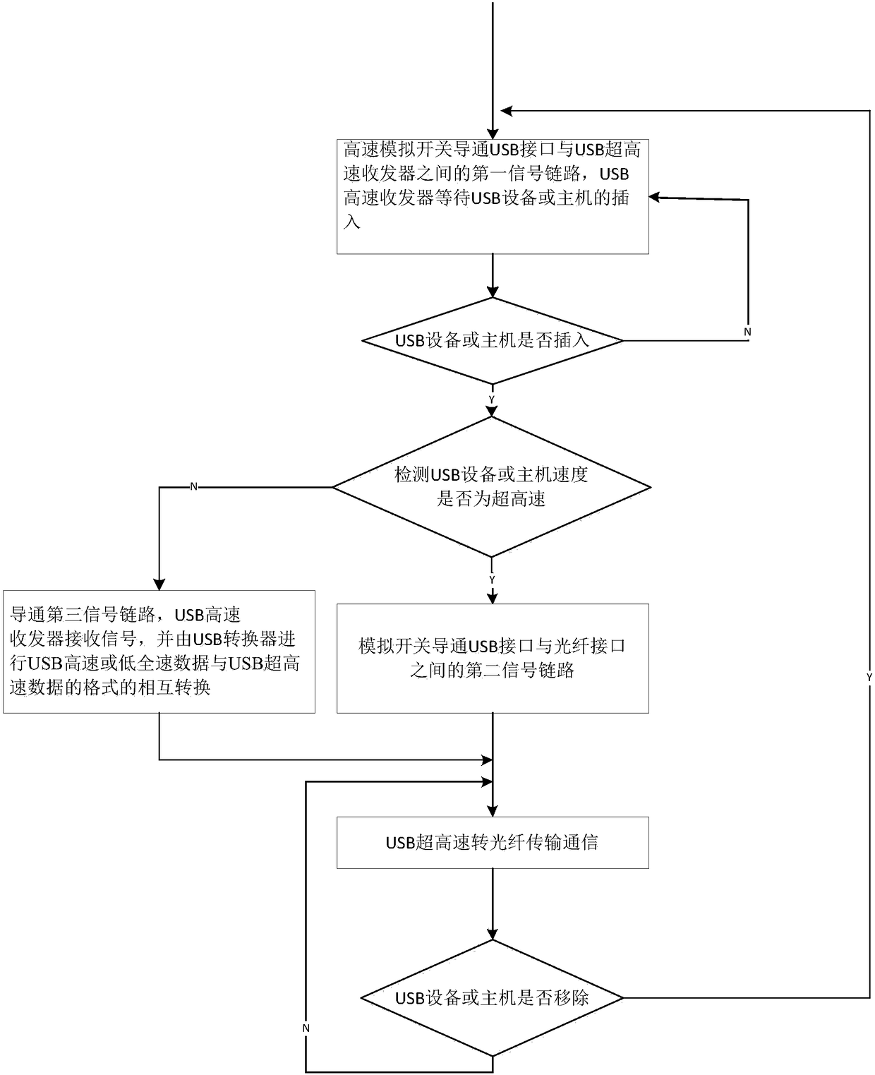
The invention discloses an optical fiber transmission device and method for a USB (Universal Serial Bus) interface. The device comprises the USB interface and an optical fiber interface, and further comprises a USB high-speed transceiver, wherein the USB high-speed transceiver is connected with the USB interface; the USB high-speed transceiver is connected with a USB converter; the USB converter is connected with a USB ultrahigh-speed transceiver; the USB ultrahigh-speed transceiver is connected with a first interface of a high-speed analog switch; and a second interface and a third interfaceof the high-speed analog switch are respectively connected with the optical fiber interface. USB high-speed or low-full-speed data of the optical fiber transmission device can be directly extended through an optical fiber cable, and the USB high-speed or low-full-speed data and USB ultrahigh-speed data can share transmitting and receiving channels for the USB ultrahigh-speed data; and therefore, detection of plugging and unplugging of USB equipment or USB host is implemented, speed detection of the USB equipment or USB host is realized, and full-function extension of the USB interface is realized.

Description

technical field [0001] The invention relates to the field of optical fiber transmission of USB data, in particular to an optical fiber transmission device and method for a USB interface. Background technique [0002] In the prior art, using optical fiber to transmit the signal of the USB 3.0 interface will encounter two problems: 1. The existing USB 3.0 is compatible with the signal of USB 2.0, and the characteristics of the signal of USB 3.0 and USB 2.0 are different. Therefore, when using The USB 3.0 interface for signal transmission requires a pair of optical fibers to transmit data of USB 2.0 and USB 3.0 / 3.1 specifications. This transmission method will increase the number of photoelectric transceiver devices, increase system power consumption and cost, and is not convenient for users to use. 2. The physical signal of USB2.0 data cannot be directly transmitted through optical fiber, and generally requires optical fiber transmission after format conversion. [0003] CN1...

Claims


Application Information

Patent Timeline
IPC IPC(8): H04B10/25H04B1/40
CPCH04B1/40H04B10/25891
Inventor 王春华
Owner NANJING QINHENG MICROELECTRONICS CO LTD
Learn More