Engine igniter start interlocking control system and control method thereof

A control system and igniter technology, applied in engine control, machine/engine, mechanical equipment, etc., can solve problems such as start interlock failure, difficulty in accurately judging engine status, damage to igniter controller, etc., to ensure safety and Reliability, ease of control method, and simple control system

Active Publication Date: 2018-10-02
苏州半唐电子有限公司
View PDF8 Cites 0 Cited by
  • Summary
  • Abstract
  • Description
  • Claims
  • Application Information

AI Technical Summary

Problems solved by technology

However, due to the control principle of the sensorless permanent magnet motor itself, it is difficult to accurately judge the engine state when the ignition is started, and it is easy to fail the start interlock, which will lead to the damage of the igniter controller.

Method used


Image

  • Engine igniter start interlocking control system and control method thereof
  • Engine igniter start interlocking control system and control method thereof
  • Engine igniter start interlocking control system and control method thereof

Examples


Embodiment 1

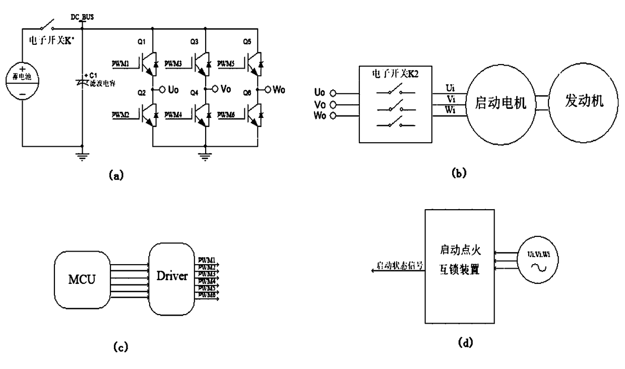
[0036] See figure 1 As shown in (a) and (b), an engine igniter starting interlock control system includes a battery electrically connected to each other, an inverter, a starter motor connected to the engine, and an MCU controller for controlling starting; wherein , the starter motor is a sensorless permanent magnet synchronous motor; a first electronic switch K1 is connected between the battery and the inverter, and a second electronic switch K2 is connected between the inverter and the starter motor;

[0037] see further figure 1 As shown in (d), the voltage output terminal of the starter motor is connected to the igniter starter interlock device, and the igniter starter interlock device outputs the start state signal of the starter motor, and controls the first electronic switch K1 or the second electronic switch according to the start state signal. Whether the switch K2 is disconnected.

[0038]In this embodiment, as a three-phase PWM converter, the inverter includes a sw...

Embodiment 2

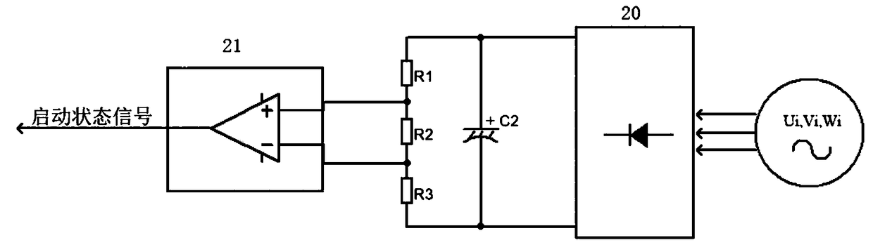
[0046] The rest of the present embodiment 2 is the same as the embodiment 1, and the difference is: please refer to image 3 As shown, in this embodiment 2, the igniter starting interlocking device includes an uncontrolled rectifier 20, a voltage dividing resistor and a differential amplifier 21 that are electrically connected in sequence, wherein the three-phase voltage output terminal U of the starting motor i , V i , W i Connecting to the uncontrolled rectifier 20, preferably, in this embodiment, the uncontrolled rectifier 20 adopts a rectifier diode device; the uncontrolled rectifier 20 is connected in parallel with a filter capacitor C2; the output end of the differential amplifier 21 outputs a start-up state signal;

[0047] The control method of the engine igniter start-up interlock control system in the second embodiment, the operation steps of which include:

[0048] B10), the MCU controller determines the change of the engine speed according to the change of the st...

Embodiment 3

[0053] The rest of the present embodiment 3 is the same as the embodiment 1, and the difference is: please refer to Figure 4 As shown, in this embodiment 3, the igniter starting interlocking device includes an uncontrolled rectifier 30 and an electromagnetic switch 31 that are electrically connected to each other, wherein the three-phase voltage output end U of the starting motor i , V i , W i The uncontrolled rectifier 30 is connected. Specifically, preferably, in this embodiment, the uncontrolled rectifier 30 adopts a rectifier diode device; the uncontrolled rectifier 30 is connected in parallel with the filter capacitor C3;

[0054] In the third embodiment of the present invention, the control method of the engine igniter start interlock control system as described above, the operation steps of which include:

[0055] C10), the MCU controller determines the change of the engine speed according to the output DC voltage change of the uncontrolled rectifier 30 in advance, a...


PUM


Abstract

The invention discloses an engine igniter start interlocking control system and a control method thereof. The system comprises a storage battery, an inverter and a starting motor which are mutually electrically connected, and an MCU used for controlling starting. The starting motor is a sensorless permanent-magnet synchronous motor. A first electronic switch is connected between the storage battery and the inverter, and / or second electronic switches are connected between the inverter and the starting motor. The voltage output end of the starting motor is connected to an igniter start interlocking device. The igniter start interlocking device outputs a start state signal of the starting motor, and it is judged that whether the first electronic switch and / or the second electronic switches are / is controlled to be turned off or not according to the start state signal. According to the engine igniter start interlocking control system and the control method thereof, the state of an engine atthe time of ignition starting can be accurately judged, accordingly, an ignition interlocking function of the engine is reliably achieved according to the state of the engine, the control system provided by the invention is simple, the control method is easy to achieve, and in addition, the safety and reliability of the igniter controller at the time of starting of the engine can be effectively guaranteed.

Description

technical field [0001] The invention belongs to the field of engine control, in particular to an engine igniter start-up interlock control system, and the invention also relates to a control method for the engine igniter start-up interlock. Background technique [0002] The function of the engine igniter of many vehicles such as motorcycles and automobiles is to convert the DC power provided by the low-voltage battery through the power electronic conversion to output the AC power to drive the starter motor to drive the engine to accelerate to a certain speed to achieve ignition. In order to prevent the high-voltage back EMF from the high-speed rotating starter motor from entering the igniter controller with lower withstand voltage after the ignition is completed and damaging the device, it is necessary to effectively disconnect the ignition controller and the starter motor through the switch after the ignition is completed to realize the igniter. Start interlock to ensure sa...

Claims


Application Information

Patent Timeline
IPC IPC(8): F02D37/02
CPCF02D37/02
Inventor 田磊何志明向大为
Owner 苏州半唐电子有限公司
Why Eureka
Try Eureka