Emission pollutant treatment system and method applied to gasoline engine

A pollutant treatment and gasoline engine technology, applied in engine components, engine control, machines/engines, etc., can solve the problems of reduced catalytic conversion efficiency of after-treatment systems, deterioration of power and economy, and increase of original engine emissions. Improved catalytic conversion efficiency, good fuel atomization, and reduced raw emissions

Inactive Publication Date: 2018-10-02
ZHEJIANG GEELY HLDG GRP CO LTD +1
View PDF5 Cites 3 Cited by
  • Summary
  • Abstract
  • Description
  • Claims
  • Application Information

AI Technical Summary

Problems solved by technology

However, this kind of optimization will have the following disadvantages: 1. Increased cost: 600-1000 yuan per engine; 2. Deterioration of power and economy; 10-18Kpa increase; 4. After durability, the back pressure increases 20-40Kpa compared with the original machine; 5. The power attenuation is about 3%, and the economy is about 1.5% lower
[0004] The current air flow measurement is obtained through the measurement of the intake air temperature and pressure sensor. Under transient conditions, the sharp change of the intake air temperature and pressure caused by the change of the throttle opening will distort the air flow measurement under transient conditions. At this time, the accuracy of the air-fuel ratio adjusted by the oxygen sensor is very poor, and there is a large error between the actual air-fuel ratio and the preset air-fuel ratio, resulting in a decrease in the catalytic conversion efficiency of the after-treatment system and deterioration of emissions; Under normal circumstances, the time for the engine oxygen sensor to enter the closed loop is very long. Depending on the model, it is about 150 to 300 seconds at idle speed. The extremely long closed loop time will cause the air-fuel ratio in this stage to be relatively rich, and the original engine emissions will greatly increase. In addition, due to the thicker fuel injection, the fuel consumption will also increase

Method used


Image

  • Emission pollutant treatment system and method applied to gasoline engine
  • Emission pollutant treatment system and method applied to gasoline engine

Examples


Embodiment Construction

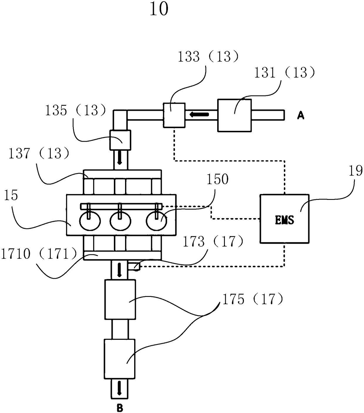
[0027] In order to further explain the technical means and effects of the present invention to achieve the predetermined purpose, the following in conjunction with the accompanying drawings and preferred embodiments, the specific implementation of the exhaust pollutant treatment system and method applied to gasoline engines proposed according to the present invention , structure, feature and effect thereof, detailed description is as follows.

[0028] The aforementioned and other technical contents, features and effects of the present invention will be clearly presented in the following detailed description of the preferred embodiments with reference to the drawings. Through the description of the specific implementation, the technical means and effects of the present invention to achieve the intended purpose can be understood more deeply and specifically, but the accompanying drawings are only for reference and description, and are not used to limit the present invention .

...


PUM


Abstract

The invention discloses an emission pollutant treatment system and method applied to a gasoline engine. The system comprises a gas inlet system, an engine, an exhaust aftertreatment system and an electric control system which are connected in sequence. The gas inlet system is used for precisely measuring the air flow and feeding back signals to the electric control system. The electric control system is used for receiving the signals and cooperating with an oxygen sensor in the exhaust aftertreatment system to precisely control the air-fuel ratio. The engine comprises a fuel injection system mounted in an engine body, and the fuel injection system is used for precise fuel injection atomization. According to the system and method, the arrangement structure is optimized, the technological level is increased, and therefore original emissions are reduced, and the aim of the emission regulation (CHINA 6) is achieved under the condition of not utilizing GPF.

Description

technical field [0001] The invention relates to the technical field of engine pollutant treatment, in particular to a system and method for treating exhaust pollutants applied to gasoline engines. Background technique [0002] In order to deal with the increasingly serious environmental pollution, my country promulgated the national six-stage vehicle emission regulations "GB18352.6-2016". Compared with the current National V standards, this regulation has leapfrogly improved both in the test conditions and in the emission limits. For gasoline engines, the requirement of PN (Particulate Number) value is added. For gasoline engines, especially direct injection gasoline engines, the PN value, which has never been considered before, will become the biggest challenge for the whole vehicle to meet emission regulations. In order to meet the PN value of emission regulations and the limit requirements of other pollutants, new technologies must be applied to reduce engine emission v...

Claims


Application Information

Patent Timeline
Patent Type & Authority Applications(China)
IPC IPC(8): F02D41/14F02D41/06F02D41/18F02D41/38F01N3/28
CPCF01N3/28F02D41/064F02D41/1454F02D41/182F02D41/38
Inventor 张书恩陆经文杨林李连豹韦虹李双清李军王瑞平
Owner ZHEJIANG GEELY HLDG GRP CO LTD
Why Eureka
Try Eureka