

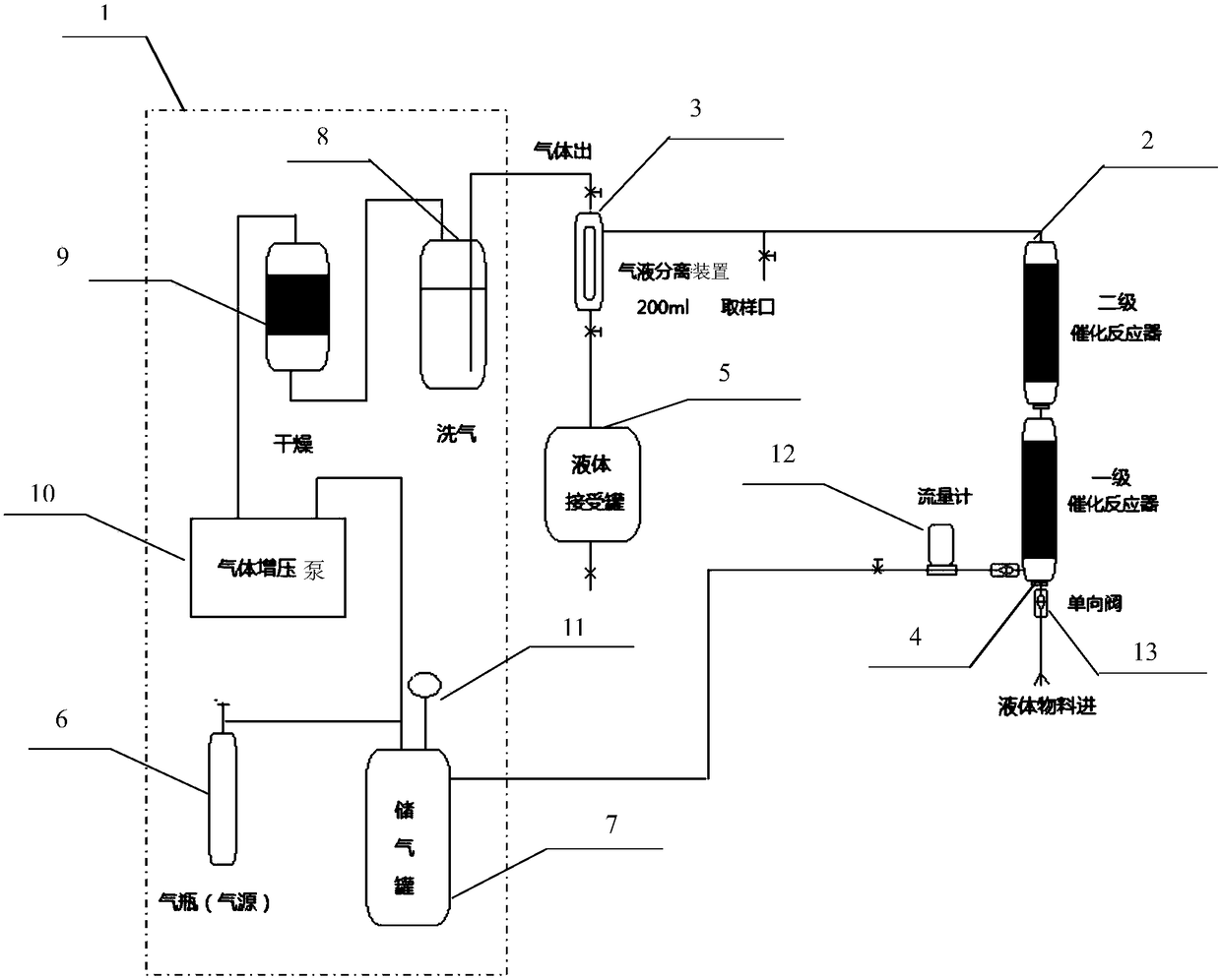
Continuous hydrogenation reduction reaction system
A reaction system and reaction technology, which are applied in the preparation of sugar derivatives, sugar derivatives, sugar derivatives, etc., can solve the problems of prolonged reaction period, large area of the reaction kettle, and increased sealing difficulty, and reduce the number of reaction steps. , shorten the production cycle, the effect of small volume requirements
- Summary
- Abstract
- Description
- Claims
- Application Information
AI Technical Summary
Problems solved by technology
Method used
Image

Examples
Embodiment 1
[0030] Example 1 2-chlorouracil is reduced to 2-deoxyuracil
[0031] 1) Add the solid-loaded nickel catalyst into the catalytic reactor. Assemble all the components, pass in 0.2mpa nitrogen gas, check the air tightness, and proceed to the next step if there is no air leakage.
[0032] 2) Add 3kg of 2-chlorouracil to 60kg of methanol to form a 5% methanol solution.
[0033] 3) The whole system is fed with nitrogen gas of 0.1 MPa and vacuumed for three times, then vacuumed and fed with hydrogen gas of 0.1 MPa. Vacuumize, and then the gas storage tank 7 is fed with hydrogen to be constant at 2.0mpa.
[0034] 4) Open the valve of the one-way valve 13 of the liquid material inlet 4 and start to feed pure water, and adjust the valve of the one-way valve 13 of the liquid material inlet 4 to stabilize the feed rate at 20ml / min.
[0035] 5) Turn on the gas booster pump 10, adjust the flow meter 12 to make the gas velocity reach 30 L / min, and then adjust the gas outlet valve of the g...
Embodiment 2
[0039] Embodiment 2 Nitrobenzene is reduced to aniline
[0040] 1) Add the solid-loaded nickel catalyst into the catalytic reactor. Assemble all the components, pass in 0.2mpa nitrogen gas, check the air tightness, and proceed to the next step if there is no air leakage.
[0041] 2) Add 1kg of nitrobenzene to 5kg of ethanol to make a 20% ethanol solution. A nickel catalyst that has been solidly loaded is added into the catalytic reactor.
[0042] 3) The whole system is fed with nitrogen gas of 0.1 MPa and vacuumed for three times, then vacuumed and fed with hydrogen gas of 0.1 MPa. Vacuumize, and then the gas storage tank 7 is fed with hydrogen to be constant at 2.0mpa.
[0043] 4) Open the valve of the one-way valve 13 of the liquid material inlet 4 and start to feed pure water, and adjust the valve of the one-way valve 13 of the liquid material inlet 4 to stabilize the feed rate at 50ml / min.
[0044] 5) Turn on the gas booster pump 10, adjust the flow meter 12 to make the ...
PUM
 Abstract
Description
Claims
Application Information