Comb slot machine tool and comb slot cutter displacement control method thereof

A technology for combing grooves and machine tools, applied in the direction of gear cutting machines, mechanical equipment, manufacturing tools, etc., can solve the problems of difficult speed control, cumbersome overall structure, certain stroke, etc., to achieve the effect of convenient operation and simplified overall structure

Active Publication Date: 2018-10-23
上海星合机电有限公司
View PDF6 Cites 4 Cited by
  • Summary
  • Abstract
  • Description
  • Claims
  • Application Information

AI Technical Summary

Problems solved by technology

[0008] 1. Because the length of the crankshaft moves, its stroke is fixed, which makes it inconvenient to adjust the stroke;
[0009] 2. During the rotation of the crank shaft, when the pendulum and its connection point move to the highest point and the lowest point, its instantaneous speed is zero, and when it moves to the middle position, its speed is the fastest. Therefore, during the whole movement process, its speed It is in the reciprocating process of acceleration-deceleration-acceleration-deceleration, so the whole cutting process is in an uneven cutting process, and the speed is difficult to control;
[0010] 3. The crank shaft can only provide the up and down reciprocating movement of the combing knife. When it is necessary to adjust the vertical position of the tool holder body assembly, it needs to realize the up and down movement of the sliding seat. In the technical solution disclosed in the above invention, the sliding seat moves up and down Need to add another set of ball screw device, so the overall structure is more bulky and complicated

Method used


Image

  • Comb slot machine tool and comb slot cutter displacement control method thereof
  • Comb slot machine tool and comb slot cutter displacement control method thereof
  • Comb slot machine tool and comb slot cutter displacement control method thereof

Examples


Embodiment Construction

[0046] The present invention will be described in further detail below in conjunction with the accompanying drawings.

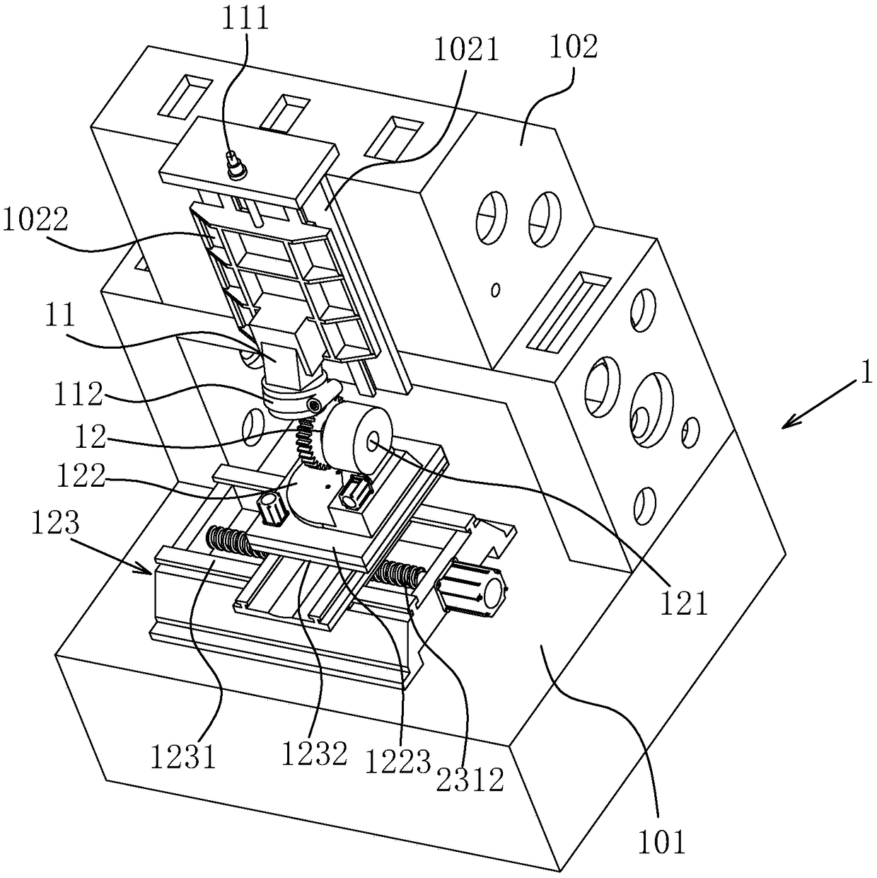
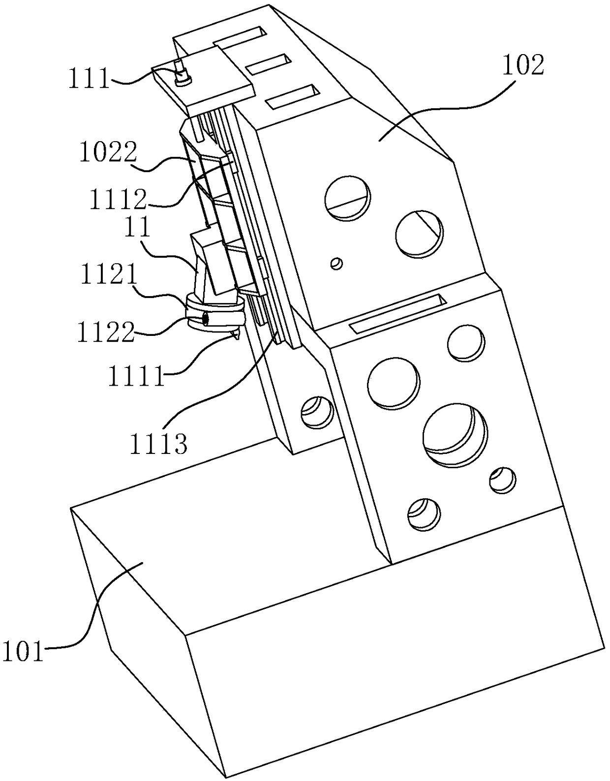
[0047] Grooving lathe disclosed by the present invention, such as figure 1 As shown, it includes an "L"-shaped bed 1, and the bed 1 includes a horizontal platform 101 in the horizontal direction and a vertical wall 102 in the vertical direction. Such as figure 1 As shown, a fixed seat 1021 is fixed on the vertical wall surface 102, and a sliding seat 1022 is vertically slidably connected to the fixed seat 1021. The lower part of the sliding seat 1022 is connected with a knife rest body assembly 11, and the knife rest body assembly 11 fixes the comb groove knife 1111 (see figure 2 );Such as figure 1 As shown, the workpiece seat 12 for fixing the gear shaving cutter workpiece is fixed on the horizontal platform 101, and the workpiece seat 12 is located below the tool rest body assembly 11, as figure 1 As shown, the workpiece seat 12 is connected with a hor...


PUM


Abstract

The invention discloses a comb slot machine tool and a comb slot cutter displacement control method thereof. The comb slot machine tool comprises a machine body provided with a cutter holder assembly,a comb slot cutter is fixed to the cutter holder assembly, a workpiece base is arranged below the cutter holder assembly, the cutter holder assembly is in sliding connection with the machine body anddrives the machine tool to do reciprocating motion in the vertical direction through a linear motor, the workpiece base is connected with a transverse shaft rotating mechanism, a longitudinal shaft rotating mechanism is connected to the lower portion of the transverse shaft rotating mechanism, a coordinate displacement unit is connected to the lower portion of the longitudinal shaft rotating mechanism, and the linear motor, the transverse shaft rotating mechanism, the longitudinal shaft rotating mechanism and the coordinate displacement unit are all connected to a PLC control system. By meansof the comb slot machine tool and the comb slot cutter displacement control method, the stroke of a comb slot cutter can be conveniently adjusted, the running speed of conveniently controlled, and itis guaranteed that the comb slot cutter ascends and descends at the constant speed; and in addition, on the premise that a set of numerical control shaft device, the position of the cutter holder assembly in the vertical direction can still be adjusted, and the overall structure is simplified.

Description

technical field [0001] The invention relates to a processing machine tool for gear processing cutters, more specifically, to a comb groove machine tool for processing gear shaving cutters and a method for controlling the displacement of the comb groove cutter. Background technique [0002] The shaving cutter is a finishing tool for straight and helical involute cylindrical gears. When shaving, the cutting edge of the shaving knife shaves a thin layer of metal along the tooth surface of the workpiece, which can effectively improve the precision and tooth surface quality of the shaved gear. [0003] The Chinese invention patent with the application publication number of CN103878443A discloses a machine tool for processing chip pockets of shaving cutters, which includes a bed, a middle bed, a column, a sliding seat, a tool holder body assembly, an indexing head, and a transverse slide table , and a numerical control system and a hydraulic system, wherein the bed and the founda...

Claims


Application Information

Patent Timeline
Patent Type & Authority Applications(China)
IPC IPC(8): B23F19/06B23F23/12B23Q1/00
CPCB23F19/06B23F23/1237B23Q1/0009
Inventor 蒋能唐钧周立坤
Owner 上海星合机电有限公司
Why Eureka
Try Eureka