
An automatic processing method for precision forging stator blades
A stator blade and processing method technology, applied in metal processing equipment, manufacturing tools, milling machine equipment, etc., can solve the problems of complex process, low processing efficiency, low pass rate of blade profile, etc., and achieve good stability and processing accuracy High, unobstructed walking path
- Summary
- Abstract
- Description
- Claims
- Application Information
AI Technical Summary
Problems solved by technology
Method used
Image

Examples
Embodiment Construction
[0040] The present invention is described in further detail below in conjunction with accompanying drawing:
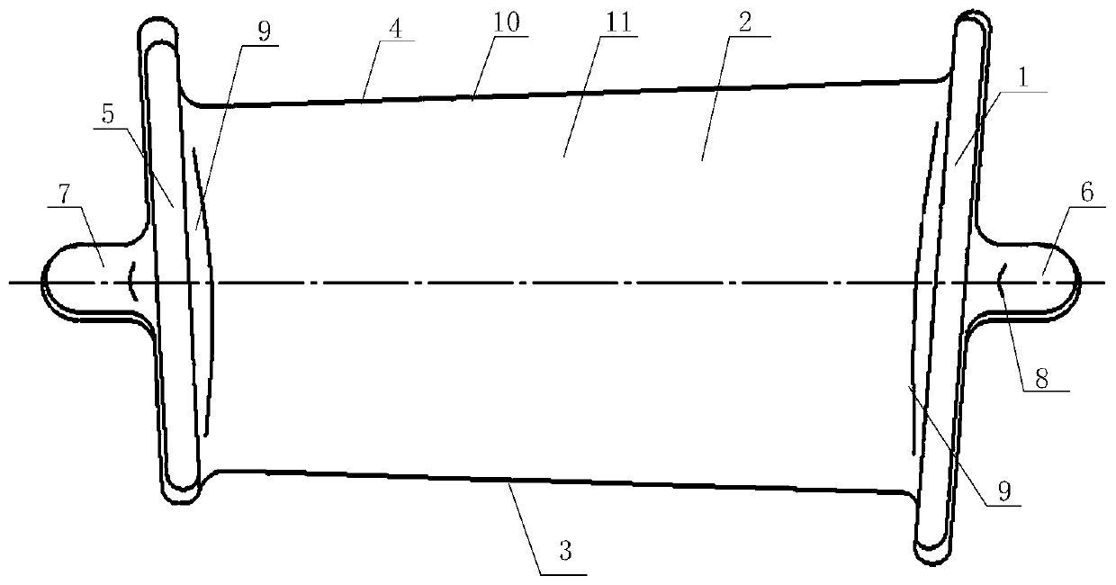
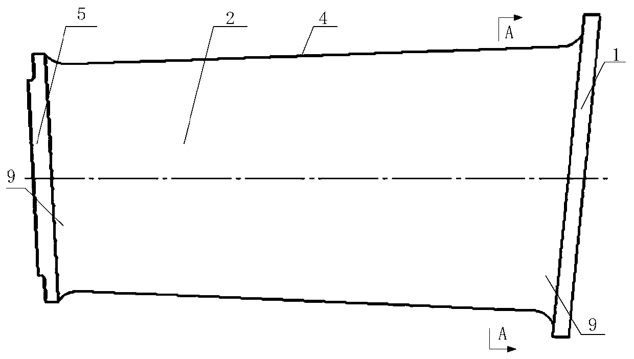
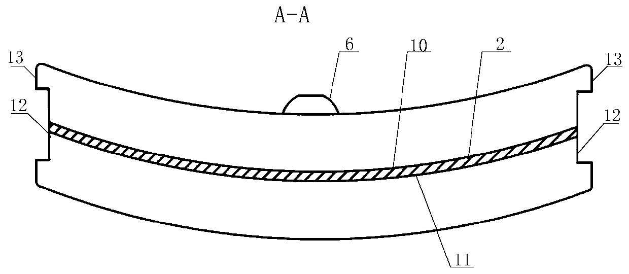
[0041] see figure 1 and image 3 , the engine stator blank blade of the present invention is a precision forging, and the blank blade includes an upper edge plate 1, a blade body 2, an exhaust edge 3, an air intake edge 4, a lower edge plate 5, a process upper boss 6, and a process lower boss 7 , transfer arc surface 9; the concave surface of the blade body 2 is the blade basin 10, and the convex surface of the blade body 2 is the blade back 11; one side of the blade body 2 is the exhaust edge 3, and the other side is the air intake edge 4; One end of 2 is the upper edge plate 1, and the other end is the lower edge plate 5; the outer surface of the upper edge plate 1 is fixedly connected with the upper boss 6 of the process, and the outer side of the lower edge plate 5 is fixedly connected with the lower boss 7 of the process. The fixed surface of the lower edge plat...
PUM
 Abstract
Description
Claims
Application Information