Movable biomass cogeneration device

A combined heat and power generation and mobile technology, which is applied in the direction of hot gas variable displacement engine devices, machines/engines, lighting and heating equipment, etc., can solve the problems of scattered biomass resources, high transportation costs, difficult collection, etc., and achieve flexibility , Improve energy utilization efficiency and realize the effect of distributed utilization

Inactive Publication Date: 2018-11-20
HUANENG CLEAN ENERGY RES INST
View PDF0 Cites 4 Cited by
  • Summary
  • Abstract
  • Description
  • Claims
  • Application Information

AI Technical Summary

Problems solved by technology

[0006] The purpose of the present invention is to provide a mobile biomass heat and power cogeneration device, which solves the current problems of scattered biomass resources, difficult collection, and high transportation costs, so as to realize the distributed utilization of energy

Method used


Image

  • Movable biomass cogeneration device

Examples


Embodiment Construction

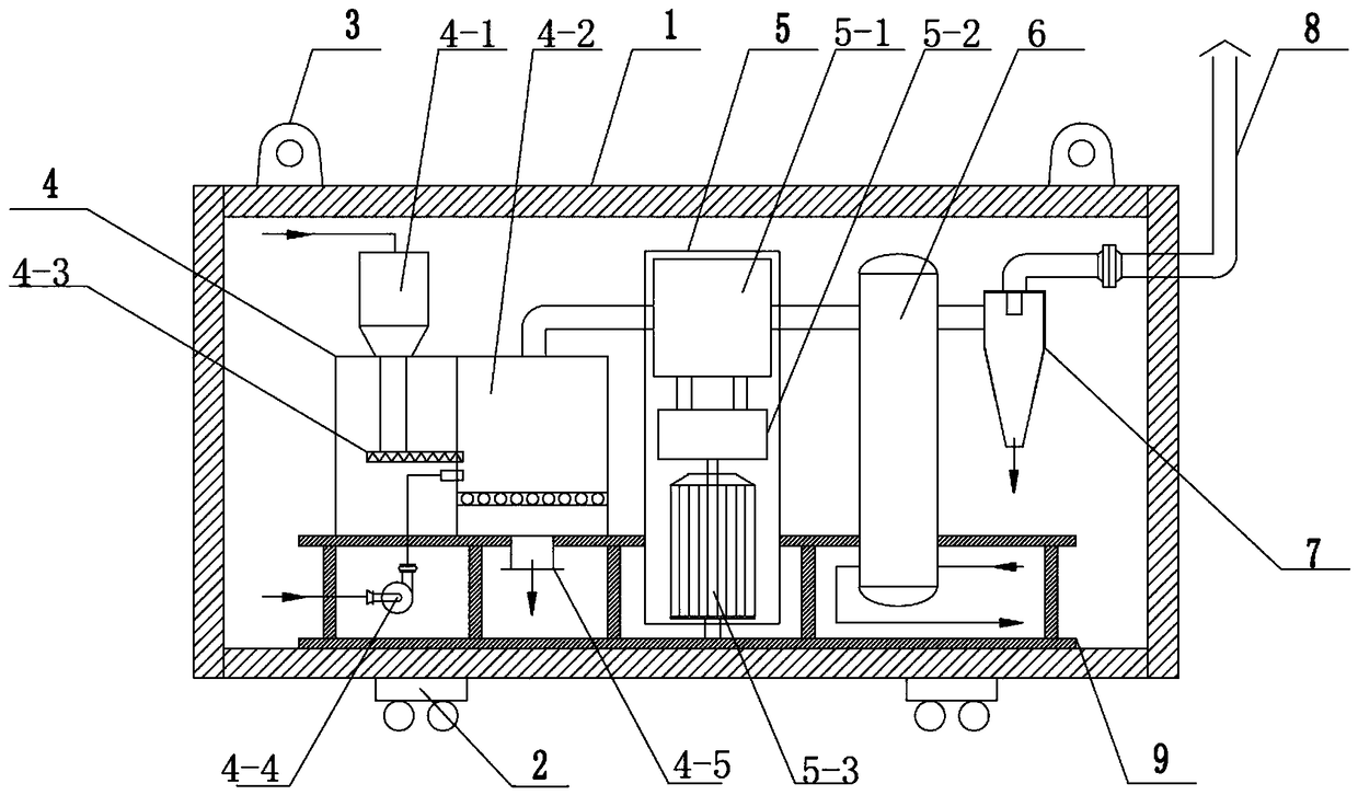
[0023] Such as figure 1 As shown, the present invention provides a movable biomass cogeneration device, comprising a movable header 1, a biomass combustion furnace 4, a heat generator, a heating system and an exhaust gas treatment system, and the movable header 1 It is a cuboid structure, and the six faces of the movable header 1 are fixedly connected by bolts. The top of the movable header 1 is symmetrically provided with 2-4 lifting lugs 3, and the bottom of the movable header 1 is symmetrically arranged with 4 Set of rollers 2, the rollers 2 are threadedly connected to the bottom of the movable header 1, and the movable header 1 is equipped with a biomass burning furnace 4, a hot gas generator, a heating system and an exhaust gas treatment system, and the biomass burning furnace 4 includes The silo 4-1 and the combustion furnace 4-2, the combustion furnace 4-2 is arranged on one side of the hopper 4-1, the air blower 4-4 is arranged at the lower part of the silo 4-1, and th...


PUM


Abstract

The invention discloses a movable biomass cogeneration device. The movable biomass cogeneration device comprises a movable header, a biomass combustion furnace, a hot-gas generator, a heat supply system and a tail gas treatment system, wherein the biomass combustion furnace, the hot-gas generator, the heat supply system and the tail gas treatment system are arranged in the movable header, a smokeoutlet of the biomass combustion furnace is in matching connection with an air inlet of the hot-gas generator by virtue of a pipeline, an air outlet of the hot-gas generator is in matching connectionwith an air inlet of the heat supply system by virtue of a pipeline, an air outlet of the heat supply system is in matching connection with the tail gas treatment system by virtue of a pipeline, the movable header is of a cuboid structure, six surfaces of the movable header are fixedly connected by virtue of bolts, and two to four lifting lugs are symmetrically arranged on the top of the movable header. According to the movable biomass cogeneration device, non-petrification fuel can be burnt to generate power and supply heat, so that the energy utilization efficiency is improved, the problem of pollution of non-coal based fuel such as straws and household waste is effectively solved, and biomass cogeneration is realized.

Description

technical field [0001] The invention belongs to the technical field of power generation and heating equipment, and in particular relates to a movable biomass cogeneration device. Background technique [0002] At present, my country uses coal-fired power generation as the main method, and consumes about 1.5 billion tons of coal every year. The environmental problems caused by this are becoming more and more obvious, especially in recent years. The health of residents has been seriously endangered. [0003] Biomass is a kind of renewable energy. From the perspective of the whole process from planting to burning, the consumption of biomass energy has CO 2 Near to zero emission characteristics, and can greatly reduce SO 2 It is an effective way to promote green development, low-carbon development and control smog. The use of biomass energy for power generation can turn agricultural and forestry wastes into treasures in agricultural production, which is of great significance fo...

Claims


Application Information

Patent Timeline
Patent Type & Authority Applications(China)
IPC IPC(8): F23K3/14F23J15/02F23J15/06F02G1/043
CPCF23K3/14F02G1/043F23J15/027F23J15/06
Inventor 樊强许世森刘沅王鹏杰李小宇任永强
Owner HUANENG CLEAN ENERGY RES INST
Why Eureka
Try Eureka