
A method and device for measuring the density of a composite grouted rockfill dam based on additional mass

A technology of density measurement and additional mass, which is applied in the field of engineering geophysical exploration, can solve the problems of not showing the linear relationship of rockfill bodies, limiting the application range of the additional mass method, and large variation range

Active Publication Date: 2020-11-27
CHANGJIANG GEOPHYSICAL EXPLORATION & TESTING WUHAN CO LTD
View PDF5 Cites 0 Cited by
  • Summary
  • Abstract
  • Description
  • Claims
  • Application Information

AI Technical Summary

Problems solved by technology

[0004] Due to the large difference in engineering mechanics between the composite grout rockfill body and the pure rockfill body, the existing additional mass method technology cannot be directly applied to the density test of the composite grout rockfill body, and the additional mass method is in the application There are also some problems that limit the scope of application of the additional mass method
[0005] (1) There is no good linear relationship between the test main frequency and the additional mass under different additional mass conditions, which is common in rockfill bodies;
[0006] (2) Dynamic stiffness K and vibration mass M obtained at the same measuring point at different periods after grouting 0 The range of variation is large, and it is difficult to control the quality of test data;
[0007] (3) The frequency difference of the main frequency of each mass block is greater than 3Hz, which does not meet the test requirements of the regulations and specifications

Method used


Image

  • A method and device for measuring the density of a composite grouted rockfill dam based on additional mass
  • A method and device for measuring the density of a composite grouted rockfill dam based on additional mass
  • A method and device for measuring the density of a composite grouted rockfill dam based on additional mass

Examples


Embodiment Construction

[0031] The specific embodiments of the present invention will be described in further detail below with reference to the accompanying drawings and embodiments. The following examples are intended to illustrate the present invention, but not to limit the scope of the present invention.

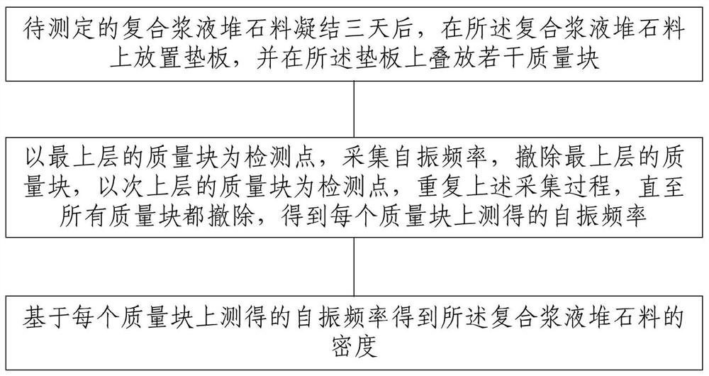
[0032] like figure 1 As shown, the figure shows a method for measuring the density of a composite slurry rockfill dam, including:

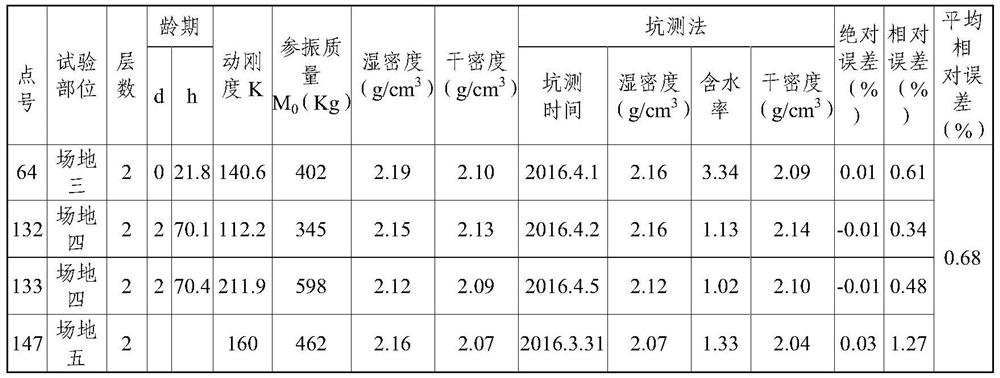
[0033] After the composite grout rockfill material to be determined is condensed, a backing plate is placed on the composite grout rockfill material, and several mass blocks are stacked on the backing plate; detection. The parameters dynamic stiffness K and paravibration mass M are tested by the additional mass method of several non-coincident measuring points on the rolling surface 0 Mathematical statistics were performed at the time points where the range of change was less than 3%, and the best on-site test time (3 days) was analyzed.

[0034] In general, th...


PUM


Abstract

The invention provides an additional mass based determination method and device for density of a composite grout rock-fill dam. The method includes the following steps: placing a backing plate on a composite grout rockfill material, after three days of coagulation of the to-be-determined composite grout rockfill material, and stacking a plurality of mass blocks on the backing plate; taking a massblock of an uppermost layer as a detection point, collecting natural vibration frequency, removing the mass block of the uppermost layer, taking a mass block of a sub-upper layer as the detection point, repeating the collection process until all the mass blocks are removed, and obtaining the measured natural vibration frequency on each of the mass blocks; and obtaining the density of the compositegrout rockfill material based on the measured natural vibration frequency on each of the mass blocks. Therefore, abnormal signals, caused by excessive surface strength of the composite grout rock-fill dam, are avoided; and test errors, caused by changes of mechanical parameters of a rockfill in a coagulation process of the composite grout rockfill material, are avoided.

Description

technical field [0001] The invention relates to the technical field of engineering geophysical prospecting, and more specifically, to a method and device for measuring the density of a composite slurry rockfill dam based on additional mass. Background technique [0002] Composite slurry rockfill material is a new type of dam building material. Specifically, the mixed slurry of cement, fine sand, additives, water and other materials is injected into the foundation dam body. Based on its easy flow and late hardening characteristics, it can fill part of the pores of the rockfill body to change the mechanical properties of the foundation dam body. , reduce the porosity of the rockfill body, and increase the compactness of the rockfill body. The compactness of the composite grout rockfill material after rolling in the early stage and grouting in the later stage is the focus of the design and construction units. Since this is a newly developed dam material, it is necessary to stu...

Claims


Application Information

Patent Timeline
Patent Type & Authority Patents(China)
IPC IPC(8): G01N9/00
CPCG01N9/00
Inventor 张建清蔡加兴马圣敏
Owner CHANGJIANG GEOPHYSICAL EXPLORATION & TESTING WUHAN CO LTD
Learn More