Check patentability & draft patents in minutes with Patsnap Eureka AI!

Power supply apparatus

A technology of power supply device and power supply control, which is applied to circuit devices, electrical components, transportation and packaging, etc., and can solve problems such as cost increase

Inactive Publication Date: 2018-11-23
JTEKT CORP
View PDF2 Cites 0 Cited by
  • Summary
  • Abstract
  • Description
  • Claims
  • Application Information

AI Technical Summary

Problems solved by technology

However, when a voltage of about 26 [V] as mentioned above is applied to the power supply IC, it is necessary to use an ECU designed for a 24V series voltage, which increases the cost

Method used


Image

  • Power supply apparatus
  • Power supply apparatus
  • Power supply apparatus

Examples


Embodiment Construction

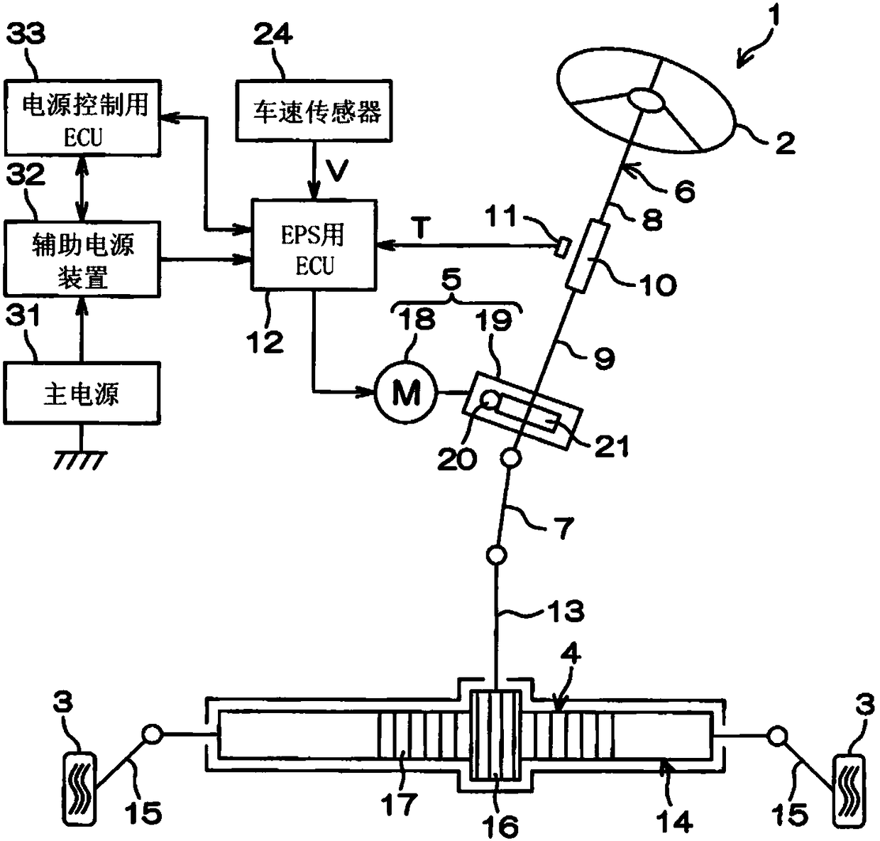
[0014] Hereinafter, embodiments of the present invention will be described in detail with reference to the drawings. figure 1 It is a schematic diagram showing a schematic configuration of an electric power steering device according to an embodiment of the present invention. An electric power steering (EPS: electric powersteering) 1 includes a steering wheel 2 , a steering mechanism 4 , and a steering assist mechanism 5 . The steering wheel 2 is a steering member for steering the direction of the vehicle. The steering mechanism 4 steers the steered wheels 3 in conjunction with the rotation of the steering wheel 2 . The steering assist mechanism 5 assists the driver's steering. The steering wheel 2 and the steering mechanism 4 are mechanically connected via a steering shaft 6 and an intermediate shaft 7 .

[0015] The steering shaft 6 includes an input shaft 8 connected to the steering wheel 2 and an output shaft 9 connected to the intermediate shaft 7 . The input shaft 8 a...


PUM


Abstract

The invention provides a power supply apparatus. In a high output voltage mode, switching elements in a charging circuit are set to OFF; a first switching element is set to ON; second and third switching elements are set to OFF; one switching element in a discharging circuit is set to ON; and another switching element in the discharging circuit is set to OFF. During a main power failure, one of the switching elements in the charging circuit is set to OFF; another of the switching elements in the charging circuit is set to ON; the first switching element is set to OFF; the second and third switching elements are set to ON; the one switching element in the discharging circuit is set to ON; and the other switching element in the discharging circuit is set to OFF.

Description

[0001] Cross References to Related Applications [0002] This application claims the priority of Japanese Patent Application No. 2017-096564 filed on May 15, 2017, and uses the entire content including its specification, drawings and abstract here. technical field [0003] The invention relates to a power supply device having a main power source and auxiliary power sources of a plurality of systems. Background technique [0004] JP 2014-150672 A discloses a power supply device for supplying power to a drive circuit of an electric motor for EPS (Electric PowerSteering: Electric Power Steering). The power supply device described in Japanese Patent Application Laid-Open No. 2014-150672 includes a main power supply, a single auxiliary power supply, a charging circuit, and a switching circuit (discharging circuit). A single auxiliary power supply is connected to the main power supply. The charging circuit charges the auxiliary power source based on the main power source. The s...

Claims


Application Information

Patent Timeline
Patent Type & Authority Applications(China)
IPC IPC(8): B62D5/04B60R16/03
CPCB60R16/03B62D5/0421H02J7/0024H02P27/06H02J2310/40H02J9/06B62D5/0484B62D5/0409B62D5/0475H02P4/00
Inventor 佐藤文彦
Owner JTEKT CORP
Features
  • R&D
  • Intellectual Property
  • Life Sciences
  • Materials
  • Tech Scout
  • Unparalleled Data Quality
  • Higher Quality Content
  • 60% Fewer Hallucinations
Learn More