Motor control apparatus
A technology of motor control and motor speed, applied in the direction of motor control, motor generator control, AC motor control, etc., to achieve the effect of improved stability and wide constant power area
- Summary
- Abstract
- Description
- Claims
- Application Information
AI Technical Summary
Problems solved by technology
Method used
Image

Examples
Embodiment approach 1
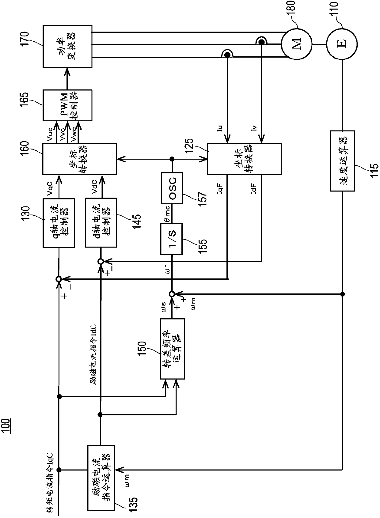
[0054] [Overall structure of the motor control device 100 ]
[0055] figure 1 It is a block diagram of the motor control device 100 of Embodiment 1.
[0056]The motor control device 100 includes a q-axis current controller 130 as a system for giving a q-axis voltage command VqC.
[0057] The q-axis current controller 130 inputs the current deviation obtained by subtracting the q-axis current feedback IqF from the input torque current command IqC, and calculates the q-axis voltage command VqC. The q-axis current feedback IqF is output from the coordinate converter 125 . The q-axis current feedback IqF is obtained by coordinate conversion of the motor currents Iu and Iv by the coordinate converter 125 based on the stator position command θmc described later. The q-axis current controller 130 is composed of a proportional-integral controller.
[0058] In addition, the motor control device 100 includes a field current command calculator 135 and a d-axis current controller 145...
Embodiment approach 2
[0105] [Overall structure of the motor control device 200 ]
[0106] Figure 4 It is a block diagram of the motor control device 200 of Embodiment 2. The motor control device 200 of Embodiment 2 adds a magnetic flux controller and a magnetic flux calculator to the structure of the motor control device 100 of Embodiment 1, and provides a magnetic flux command calculator instead of the field current command calculator 135 .
[0107] The motor control device 200 has a q-axis current controller 230 as a system for giving a q-axis voltage command VqC. The q-axis current controller 230 is the same as the q-axis current controller 130 of the first embodiment.
[0108] In addition, the motor control device 200 includes a magnetic flux command calculator 220 , a magnetic flux controller 240 , and a d-axis current controller 245 as a system for giving the d-axis voltage command VdC.
[0109] The magnetic flux command calculator 220 receives the input torque current command IqC and th...
Embodiment approach 3
[0160] [Overall structure of the motor control device 300 ]
[0161] Figure 7 It is a block diagram of the motor control device 300 of Embodiment 3. The motor control device 300 of Embodiment 3 adds a maximum primary current command calculator, a torque limit value calculator, a limiter, and a q-axis current calculator to the configuration of the motor control device 200 of Embodiment 2.
[0162] The motor control device 300 has a q-axis current controller 330 , a maximum primary current command calculator 375 , a torque limit calculator 385 , a limiter 390 , and a q-axis current calculator 395 as a system for giving a q-axis voltage command VqC. The q-axis current controller 330 is the same as the q-axis current controller 230 of the second embodiment.
[0163] The maximum primary current command calculator 375 calculates the maximum value of the primary current command supplied to the motor 380 and outputs it to the torque limit calculator 385 as the maximum primary curre...
PUM
 Abstract
Description
Claims
Application Information
 - R&D
- Intellectual Property
- Life Sciences
- Materials
- Tech Scout
- Unparalleled Data Quality
- Higher Quality Content
- 60% Fewer Hallucinations
Browse by: Latest US Patents, China's latest patents, Technical Efficacy Thesaurus, Application Domain, Technology Topic, Popular Technical Reports.
© 2025 PatSnap. All rights reserved.Legal|Privacy policy|Modern Slavery Act Transparency Statement|Sitemap|About US| Contact US: help@patsnap.com