
A Measurement Time Delay Correction Method of Flue Gas Online Continuous Monitoring System

A monitoring system and time-delay correction technology, which is applied in the direction of measuring devices, neural learning methods, and gas mixture analysis, can solve the problems of certain delay in monitoring, different acquisition processes, and different time delays.

Active Publication Date: 2020-12-29
ZHEJIANG UNIV
View PDF5 Cites 0 Cited by
  • Summary
  • Abstract
  • Description
  • Claims
  • Application Information

AI Technical Summary

Problems solved by technology

[0004] However, when the flue gas sampling equipment in the flue gas online continuous monitoring system is working, it needs to go through a series of devices such as sampling pipes from the time the sample gas is collected to the time when the sample gas to be tested enters the monitoring instrument for measurement and analysis, which leads to a certain delay in monitoring. The monitoring result is not the current real-time value; and because each monitoring and analysis instrument is installed in a different position and the collection process is different, the time delay of different collection processes is also different
The above problems have seriously affected the monitoring accuracy and evaluation ability of CEMS for the overall operating status of the monitored system

Method used


Image

  • A Measurement Time Delay Correction Method of Flue Gas Online Continuous Monitoring System
  • A Measurement Time Delay Correction Method of Flue Gas Online Continuous Monitoring System
  • A Measurement Time Delay Correction Method of Flue Gas Online Continuous Monitoring System

Examples


Embodiment Construction

[0053] The technical solutions in the embodiments of the present invention will be clearly and completely described below in conjunction with the accompanying drawings. Apparently, the described embodiments are only some but not all of the embodiments of the present invention. Based on the implementation cases in the present invention, all other implementation cases obtained by persons of ordinary skill in the art without making creative efforts belong to the scope of protection of the present invention.

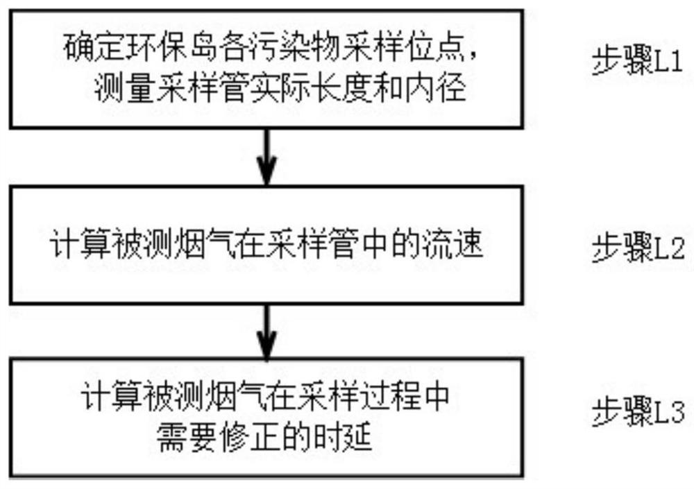
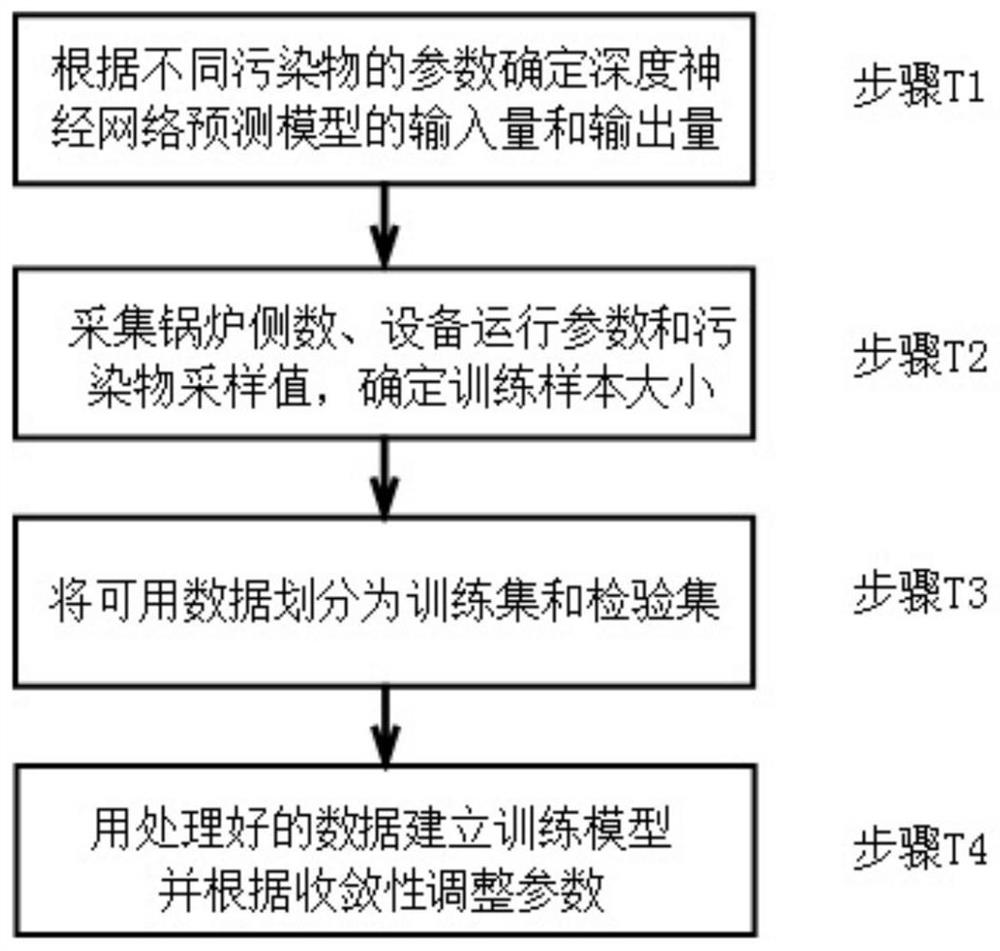
[0054] refer to Figure 1~5 , a measurement time delay correction method for the flue gas online continuous monitoring system (CEMS), which uses a neural network prediction model to correct the monitoring error caused by the time it takes for the sample gas to pass through the sampling device to reach the analysis instrument, and realize the verification The real-time and synchronous monitoring of the measured flue gas by the device ensures the real-time and effectiveness of...


PUM


Abstract

The invention provides a measurement delay correction method for an online continuous monitoring system of flue gas. The method includes the following three parts: a proposal of a time delay calculation method combining space and analysis, establishment of a prediction model and prediction of different pollutant concentrations under different sampling sections. Through measurement of the flow velocity of the flue gas in each of flue gas sampling tubes and the actual length of the sampling tubes, measurement time delay in the sampling tubes is calculated by comprehensively considering the influence of sampling instrument parameters and other factors; a neural network prediction model is established by given input and output quantities; a sampling value of a pollutant is predicted by utilizing an iterative method, and the output quantity of the last moment is used as a part of the input quantity of the next moment which is updated together with a prediction process; and historical sampling values of different pollutants are selected as the model input quantity, a true pollutant concentration value at the current moment is predicted and output. The measurement time delay correction method proposed by the invention can improve the real-time performance and accuracy of monitoring pollutants by a continuous emission monitoring system of the flue gas.

Description

technical field [0001] The invention belongs to the technical field of flue gas pollution monitoring technology, and in particular relates to a measurement time delay correction method of a flue gas on-line continuous monitoring system. Background technique [0002] With the continuous development of my country's economy, the requirements for environmental protection are gradually increasing. In order to protect the atmospheric environment and ensure that the flue gas emission industry of my country's key pollution sources can develop in a green and pollution-free direction, all relevant enterprises have installed flue gas online continuous monitoring equipment at the flue gas discharge outlet to monitor the flue gas emission in real time , to avoid air pollution. [0003] "Continuous Flue Gas Online Monitoring System" (CEMS) is a device that measures the concentration and oxygen content of pollutants such as sulfur dioxide and nitrogen oxides in flue gas by sampling, analys...

Claims


Application Information

Patent Timeline
Patent Type & Authority Patents(China)
IPC IPC(8): G01N33/00G06N3/08
CPCG01N33/0004G01N33/0037G06N3/08
Inventor 郑成航高翔黄悦琪刘少俊张涌新王毅郭一杉翁卫国吴卫红徐甸曲瑞阳张悠
Owner ZHEJIANG UNIV
Learn More