Test tube placing apparatus capable of being effectively scanned

A test tube and instrument technology, applied in the field of effective scanning test tube placement equipment, can solve the problems of cumbersome operation and large space occupation, and achieve the effect of increasing the number of samples, saving space and increasing stability

Pending Publication Date: 2018-12-18
PEKING UNION MEDICAL COLLEGE HOSPITAL CHINESE ACAD OF MEDICAL SCI
View PDF7 Cites 1 Cited by
  • Summary
  • Abstract
  • Description
  • Claims
  • Application Information

AI Technical Summary

Problems solved by technology

[0006] In order to overcome the problems of cumbersome operation and large space occupation of the test tube rack in the prior art, the present invention provides an effective scanning test tube placement device

Method used


Image

  • Test tube placing apparatus capable of being effectively scanned
  • Test tube placing apparatus capable of being effectively scanned
  • Test tube placing apparatus capable of being effectively scanned

Examples


Embodiment 1

[0051] Embodiment 1 A kind of effective scanning test tube placement instrument

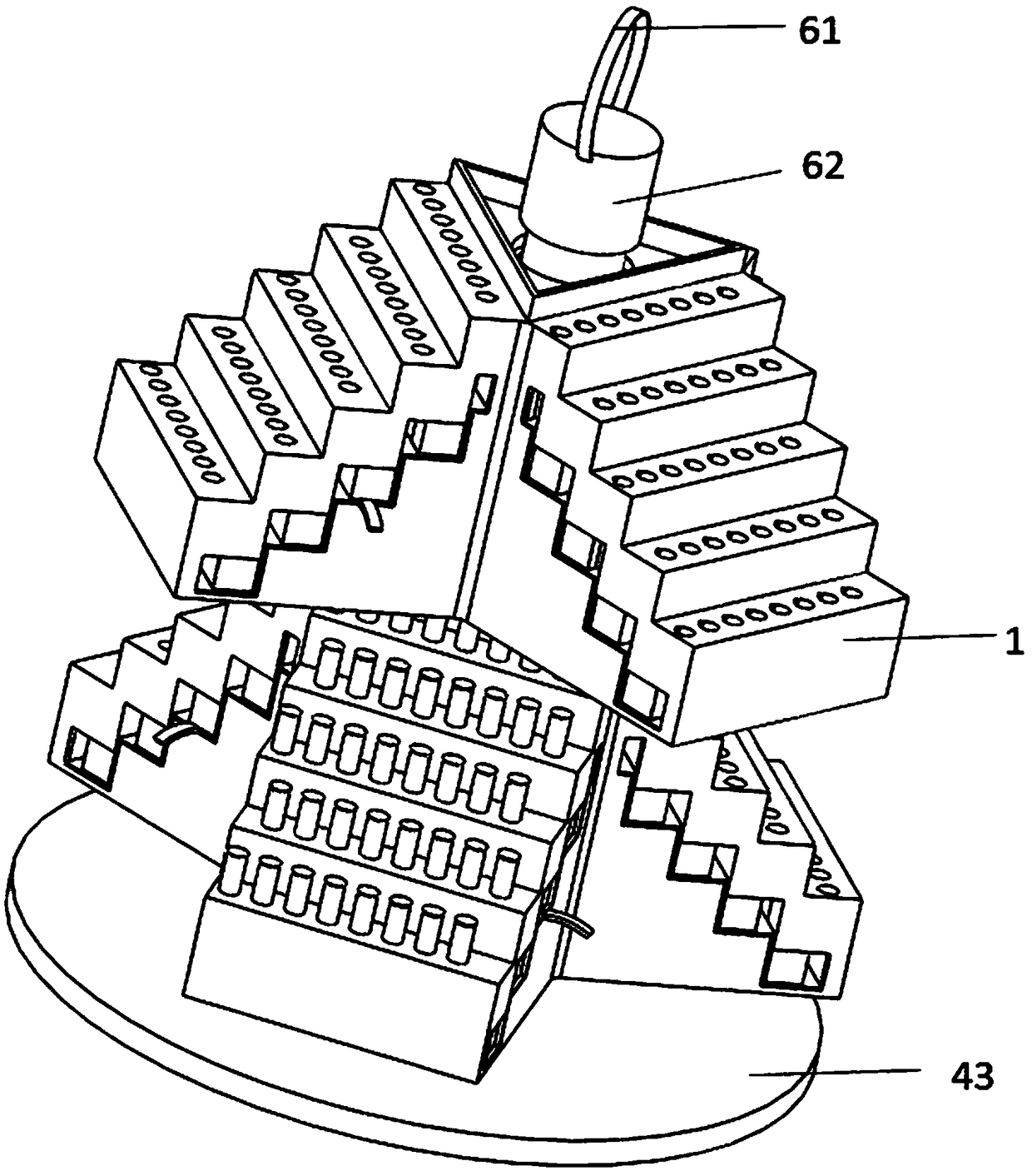
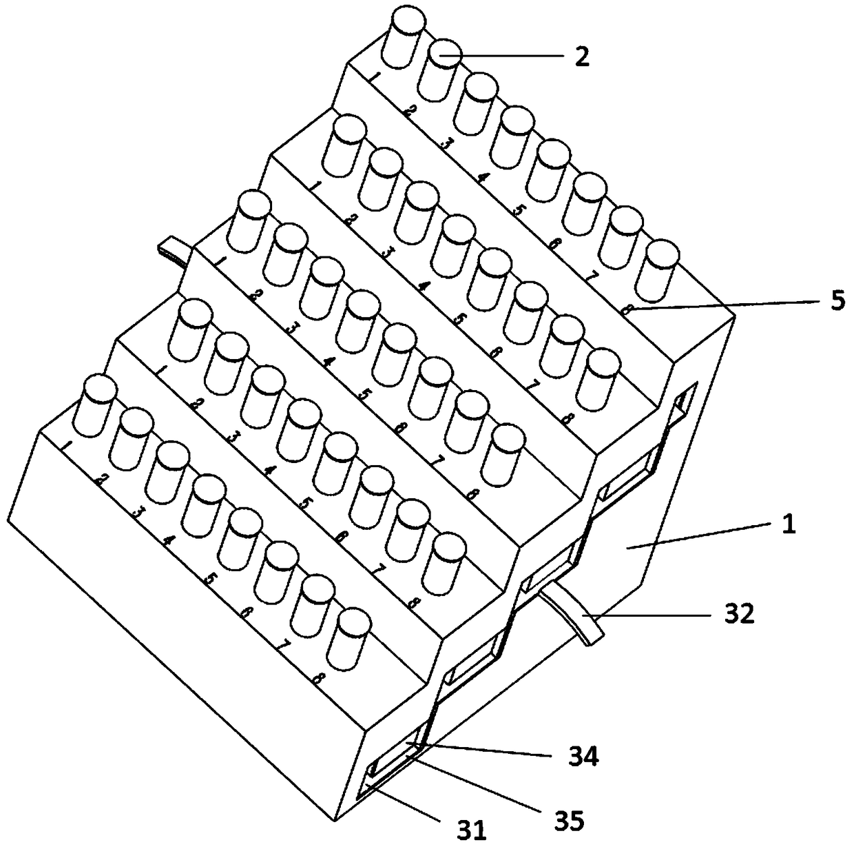
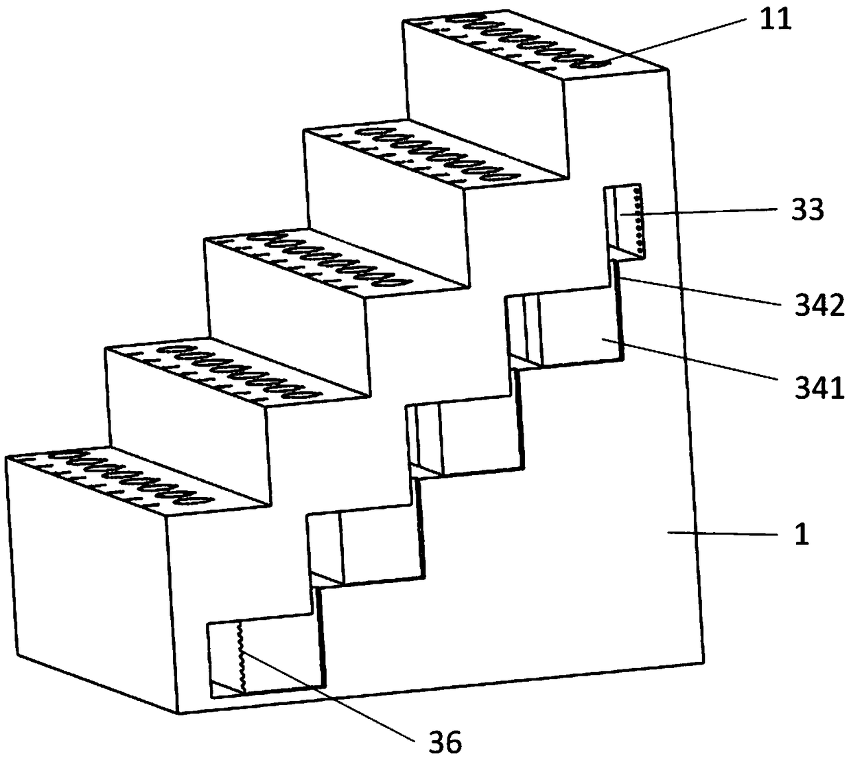
[0052] An effective scanning test tube placement instrument, which includes a stepped base 1, is characterized in that several test tube holes 11 are arranged on each step of the stepped base 1, the bottom surface of the stepped base 1 is a flat rectangle, and the depth of the test tube holes 11 is Greater than 1 / 3 of the height of the test tube 2 but less than the height from the bottom of the test tube 2 to the bottom of the two-dimensional code or barcode; the height of each step is greater than the height from the top of the test tube 2 to the bottom of the two-dimensional code or barcode on the test tube 2. This kind of setting can ensure the display of the two-dimensional code or barcode position on each layer, and ensure that the operator does not need to move or carry the test tube 2 to scan the code when scanning the code, which can effectively save the operator's time.

[0053] The test...

Embodiment 2

[0056] Embodiment 2 A kind of effective scanning test tube placement instrument

[0057] An effective scanning test tube placement instrument, which includes a stepped base 1, is characterized in that several test tube holes 11 are arranged on each step of the stepped base 1, the bottom surface of the stepped base 1 is a flat rectangle, and the depth of the test tube holes 11 is Greater than 1 / 3 of the height of the test tube 2 but less than the height from the bottom of the test tube 2 to the bottom of the two-dimensional code or barcode; the height of each step is greater than the height from the top of the test tube 2 to the bottom of the two-dimensional code or barcode on the test tube 2. This kind of setting can ensure the display of the two-dimensional code or barcode position on each layer, and ensure that the operator does not need to move or carry the test tube 2 to scan the code when scanning the code, which can effectively save the operator's time.

[0058] The test...

Embodiment 3

[0063] Embodiment 3 A kind of effective scanning test tube placement instrument

[0064] An effective scanning test tube placement instrument, which includes a stepped base 1, is characterized in that several test tube holes 11 are arranged on each step of the stepped base 1, the bottom surface of the stepped base 1 is a flat rectangle, and the depth of the test tube holes 11 is Greater than 1 / 3 of the height of the test tube 2 but less than the height from the bottom of the test tube 2 to the bottom of the two-dimensional code or barcode; the height of each step is greater than the height from the top of the test tube 2 to the bottom of the two-dimensional code or barcode on the test tube 2. This kind of setting can ensure the display of the two-dimensional code or barcode position on each layer, and ensure that the operator does not need to move or carry the test tube 2 to scan the code when scanning the code, which can effectively save the operator's time.

[0065] The test...


PUM


Abstract

The invention discloses a test tube placing apparatus capable of being effectively scanned, and the test tube placing apparatus comprises a step base. The test tube placing apparatus is characterizedin that a plurality of test tube holes are formed in each-layer step of the step base, wherein the bottom surface of the step base is in the form of a flat rectangle; depth of the test tube holes is greater than 1/3 of the height of the test tube, and smaller than height from the bottom of the test tube to a two-dimensional code bottom plate or a bar code bottom plate; height of each-layer step isgreater than the height from the top end of the test tube to a two-dimensional code bottom side or a bar code bottom side; a regulating structure capable of regulating depth of the test tube holes isadditionally arranged; the step bases are connected together, and realize conversion of different bases through a rotary shaft; and the structure with multi-layer multi-step connection further can beachieved. Appearance of the two-dimensional code position or the bar code position on each layer can be guaranteed, and an operator can directly scan the codes without the needs of moving or liftingthe test tube, so that time of the operator can be effectively prolonged.

Description

technical field [0001] The invention belongs to the technical field of clinical testing test tube rack placement devices, and in particular relates to an effective scanning test tube placement device. Background technique [0002] Many liquid samples such as blood need to be collected in the clinical examination process. Most of the liquid samples need to be placed in test tubes, and then the test tubes are placed on the test tube rack. Most of the test tube racks in the prior art are provided with multiple columns of test tube holes on a plane. The height of each test tube in the test tube rack is the same level. When the operator needs to know the patient information on the test tube, it is often necessary to take out the test tube for identification. [0003] At present, in clinical testing, QR codes or barcodes are mostly set on the test tubes, and the information is displayed on the display for identification by scanning the codes. The process of scanning codes also req...

Claims


Application Information

Patent Timeline
Patent Type & Authority Applications(China)
IPC IPC(8): B01L9/06
CPCB01L9/06B01L2200/02B01L2200/025
Inventor 刘美佳关玉霞刘丹吴东高靖勃徐茜
Owner PEKING UNION MEDICAL COLLEGE HOSPITAL CHINESE ACAD OF MEDICAL SCI
Why Eureka
Try Eureka