A circuit for generating a clock pulse signal based on alternating current

A technology of clock pulse and alternating current, which is applied in the field of synchronous control, can solve the problems of increasing product cost and volume, clock pulse signal difference, and product synchronization no longer, so as to avoid frequency deviation and timing deviation, avoid consistency, and benefit small size the effect of

Active Publication Date: 2018-12-18
黄琦
View PDF7 Cites 4 Cited by
  • Summary
  • Abstract
  • Description
  • Claims
  • Application Information

AI Technical Summary

Problems solved by technology

However, in the process of running an intelligent program, the crystal oscillator circuit unit is generally required to provide a constant frequency clock pulse signal. If you want to synchronously control more than two smart home products, such as smart lights, a family has multiple lights. If you want to synchronize To control the brightness or color changes of these lights, there will be the following technical problems: (1) If an independent communication module (such as RS232 interface or WiFi wireless communication module, etc.) is configured for each smart home product, and through these communication modules Controlling the collaborative work of multiple products will undoubtedly increase product cost and volume; (2) If these smart home products do not have independent communication modules, they can only rely on the crystal oscillator circuit unit in the product for accurate timing (that is, to provide clock pulses). signal), and realize synchronous control based on the same clock pulse signal, but in the actual application process, due to temperature changes, the frequency deviation of the crystal oscillator will occur, which will cause differences in the internal clock pulse signals of each product, which will lead to differences between products. Synchronization of is no longer possible

Method used


Image

  • A circuit for generating a clock pulse signal based on alternating current
  • A circuit for generating a clock pulse signal based on alternating current
  • A circuit for generating a clock pulse signal based on alternating current

Examples


Embodiment 1

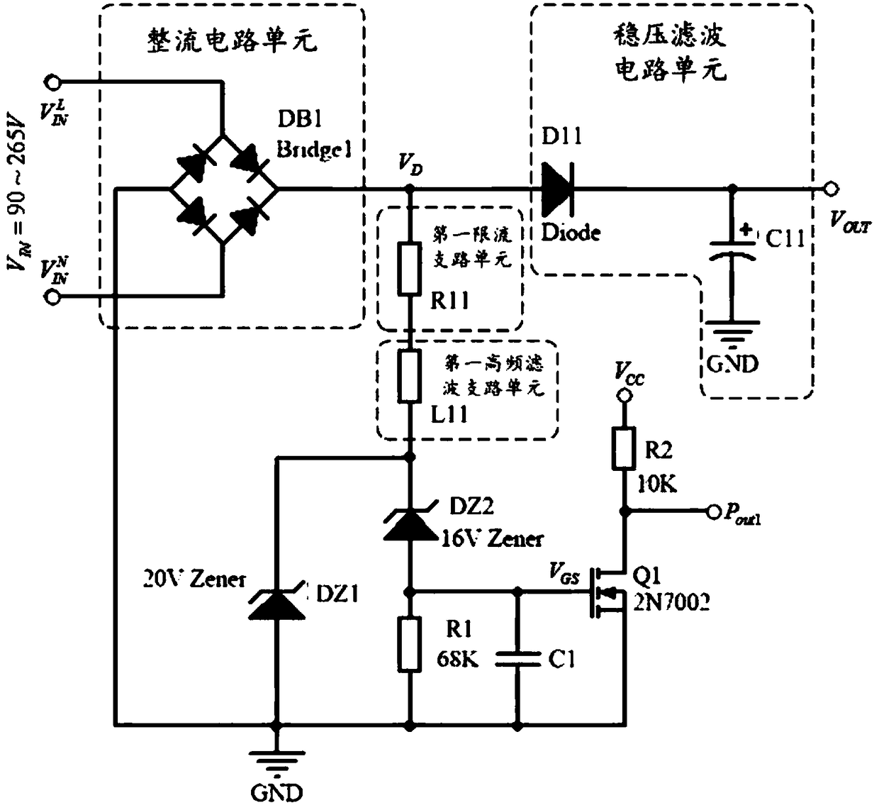
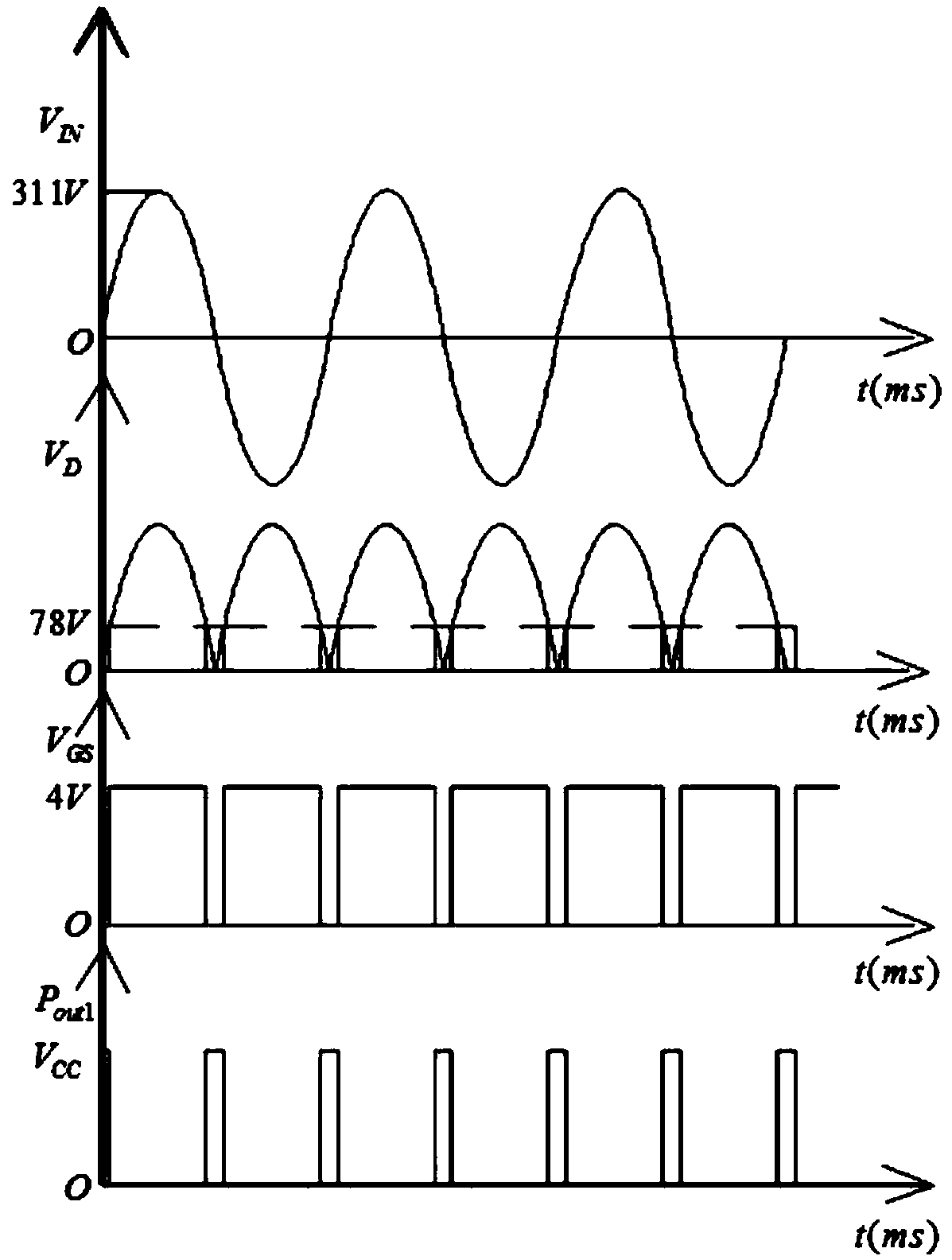
[0036] Such as figure 1 and 2 As shown, the first circuit for generating clock pulse signals based on alternating current provided in this embodiment includes a rectifier circuit unit, a voltage stabilizing filter circuit unit, a first current limiting branch unit, a first voltage stabilizing diode DZ1, a second Zener diode DZ2, first resistor R1, second resistor R2 and first field effect transistor Q1, wherein the input terminal VIN of the rectification circuit unit is used to introduce alternating current, and the output terminal of the rectification circuit unit is electrically connected to the The input terminal of the voltage stabilizing filter circuit unit, the output terminal VOUT of the voltage stabilizing filter circuit unit is used to derive direct current, the stable voltage of the first voltage stabilizing diode DZ1 is higher than the stable voltage of the second voltage stabilizing diode DZ2, The difference between the stable voltages of the first zener diode DZ1...

Embodiment 2

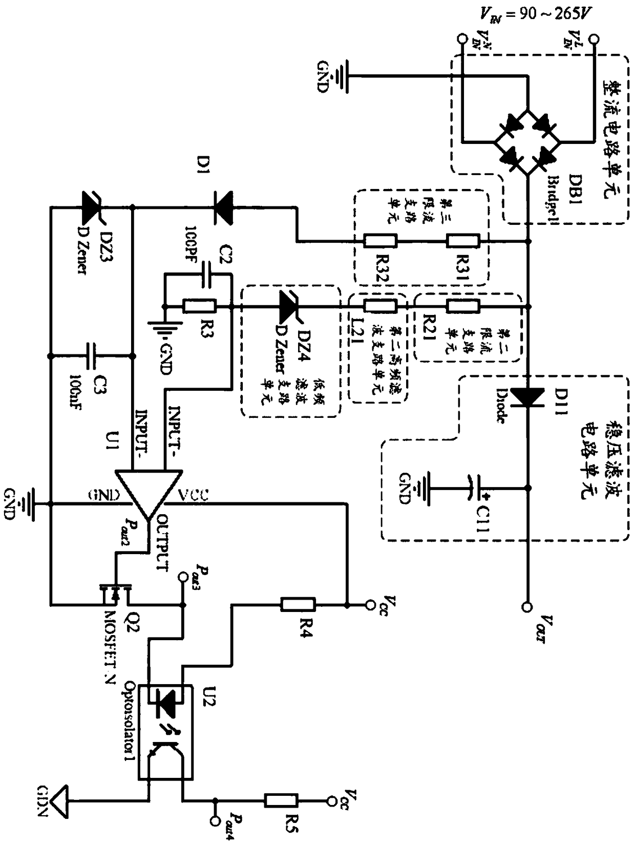
[0049] Such as image 3 As shown, this embodiment provides another circuit for generating a clock pulse signal based on alternating current. The third current-limiting branch unit, the third resistor R3, the first diode D1, the third Zener diode DZ3 and the voltage comparator U1, wherein the input terminal VIN of the rectification circuit unit is used to introduce alternating current, and the The output terminal of the rectifier circuit unit is electrically connected to the input terminal of the voltage stabilizing filter circuit unit, and the output terminal VOUT of the voltage stabilizing filter circuit unit is used to derive direct current; one end of the second current limiting branch unit and the first One end of the three current-limiting branch units is respectively electrically connected to the output end of the rectifier circuit unit, and the other end of the second current-limiting branch unit is respectively electrically connected to one end of the third resistor R3...


PUM


Abstract

The invention relates to the technical field of synchronous control and discloses a circuit for generating clock pulse signal based on alternating current. In accordance with that present invention, anovel circuit for converting an alternating current signal in a power supply network into a frequency-doubled clock pulse signal is provided, as a consequence, after the novel circuit is arranged inthe intelligent product, the output clock pulse signal can be used as the input signal of intelligent products internal counting / timing circuits and other units, therefore, not only can the crystal oscillator circuit unit be removed to avoid the frequency offset phenomenon and timing deviation caused by the working temperature, but also the same clock pulse signal can be obtained in a plurality ofintelligent products connected to the same power supply network, so as to realize the purpose of synchronously controlling a plurality of intelligent products and meet the requirements of intelligenthome. In addition, independent communication modules are not required for each intelligent product, which can reduce the cost, facilitate the volume miniaturization of the product, and avoid the influence of communication interference on the consistency of synchronization control.

Description

technical field [0001] The invention belongs to the technical field of synchronous control, and in particular relates to a circuit for generating clock pulse signals based on alternating current. Background technique [0002] In the smart home, many products are becoming more and more intelligent, that is, by running the intelligent program built into the product, the corresponding intelligent functions can be realized. However, in the process of running an intelligent program, the crystal oscillator circuit unit is generally required to provide a constant frequency clock pulse signal. If you want to synchronously control more than two smart home products, such as smart lights, a family has multiple lights. If you want to synchronize To control the brightness or color changes of these lights, there will be the following technical problems: (1) If an independent communication module (such as RS232 interface or WiFi wireless communication module, etc.) is configured for each s...

Claims


Application Information

Patent Timeline
Patent Type & Authority Applications(China)
IPC IPC(8): H03K5/003H05B37/02
CPCH03K5/003H05B47/10Y02B20/40
Inventor 黄琦
Owner 黄琦
Why Eureka
Try Eureka