Outer water discharging pump submerging and floating sand intercepting bank preventing sediment from entering water taking port

A technology for drainage pumps and water intakes, applied in water conservancy projects, sea area engineering, coastline protection, etc., can solve the problem of sediment entering water intakes, etc., and achieve the effects of wide application range, ingenious structure, and strong feasibility

Active Publication Date: 2019-01-04
SICHUAN UNIV
View PDF5 Cites 0 Cited by
  • Summary
  • Abstract
  • Description
  • Claims
  • Application Information

AI Technical Summary

Problems solved by technology

[0006] The basic idea of ​​the present invention is to design the sand-blocking sill as a sand-blocking sill whose elevation can be changed. The elevation of the sand-blocking sill in the flood season is increased, and the elevation of the sand-blocking sill in the water intake period is restored to the design elevation, so as to solve the excessive amount of the sand-blocking sill in the flood season. The problem of silting or suspended sediment entering the water intake

Method used


Image

  • Outer water discharging pump submerging and floating sand intercepting bank preventing sediment from entering water taking port
  • Outer water discharging pump submerging and floating sand intercepting bank preventing sediment from entering water taking port
  • Outer water discharging pump submerging and floating sand intercepting bank preventing sediment from entering water taking port

Examples


Embodiment Construction

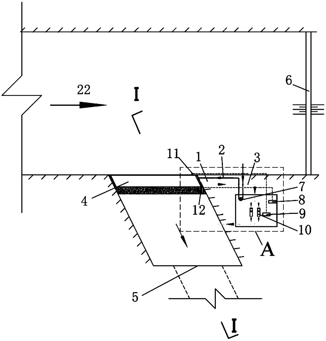
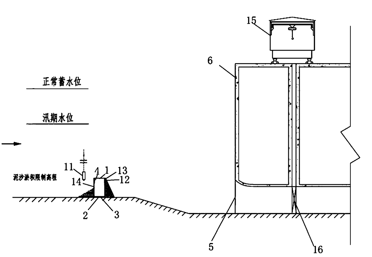
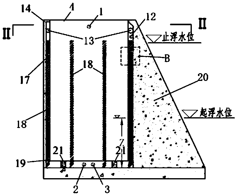
[0063] The specific embodiments of the present invention are given below in conjunction with the accompanying drawings, and the external drainage pump submersible-floating sand barrier provided by the present invention to prevent sediment from entering the water intake will be further described through the specific embodiments. It should be pointed out that the specific implementation of the present invention is not limited to the forms described in the examples.

[0064] In the following specific embodiments, the terms of directions mentioned, such as: up, down, left, right, front or back, etc., are only referring to the directions of the drawings. Therefore, the use of directional terms is for the convenience of describing the present invention, not for limiting the present invention.

[0065] The structure of the external drainage pump submersible sand-blocking sill for preventing sediment from entering the water intake in this embodiment is as follows: figure 1 - attached...


PUM


Abstract

The invention discloses an outer water discharging pump submerging and floating sand intercepting bank preventing excessive sediment from entering a water taking port. The outer water discharging pumpsubmerging and floating sand intercepting bank comprises a fixedly-arranged surrounding cavity type fixed sand intercepting bank body, a sealed submerging and floating box located in a fixed sand intercepting bank body surrounding cavity, a water discharging pump arranged outside the fixed sand intercepting bank body, a sensor for monitoring the deposition height of the sediment, a sensor for monitoring the water level and a center control unit. A body structure of the submerging and floating box and a body structure of the fixed sand intercepting bank body surrounding cavity are matched, anda guiding structure piece and a limiting structure piece limiting the floating distance of the submerging and floating box are arranged between the submerging and floating box and the fixed sand intercepting bank body surrounding cavity. According to the submerging and floating sand intercepting bank, when the sediment deposition in front of the sand intercepting bank is higher than the limitingelevation, the submerging and floating box floats, the elevation of the sand intercepting bank is increased, and after the temporary sand prevention task is finished, the submerging and floating box submerges into the fixed sand intercepting bank body surrounding cavity, and the sand intercepting normal state is recovered. According to the outer water discharging pump submerging and floating sandintercepting bank, the submerging and floating box is made to float and submerge by controlling and changing the water level in the fixed sand intercepting bank body surrounding cavity, increasing andreducing of the sand intercepting bank elevation are achieved, operation is simple, and feasibility is high.

Description

technical field [0001] The invention relates to water conservancy projects, disaster prevention and mitigation projects, agricultural water conservancy projects, etc., and in particular to a sand-blocking sill for water intakes of mountainous rivers where large sediment deposits occur in front of water intakes during flood seasons and the height of the sand-blocking sill needs to be temporarily increased. Background technique [0002] In addition to taking water from the middle and deep layers of high-dam reservoirs, more methods of water intake from mountainous rivers are low-gate water intake or no-dam water intake, and the water intake is mainly arranged laterally. In order to prevent the sediment in the river from entering the water intake, it is very important to set the location and shape of the water intake reasonably. In addition, it is also necessary to set up sand-retaining and sand-discharging structures at appropriate places in front of the water intake. Kan is t...

Claims


Application Information

Patent Timeline
Patent Type & Authority Applications(China)
IPC IPC(8): E02B8/02
CPCE02B8/023
Inventor 马旭东钟益华聂锐华刘兴年黄尔杨克君张斌王协康
Owner SICHUAN UNIV
Why Eureka
Try Eureka