fine bubble generator
A bubble generator and fine technology, applied in fluid mixers, washing machines with containers, chemical instruments and methods, etc., can solve the problems of large assembly and adjustment workload of fine bubble generators
- Summary
- Abstract
- Description
- Claims
- Application Information
AI Technical Summary
Problems solved by technology
Method used
Image

Examples
no. 1 approach
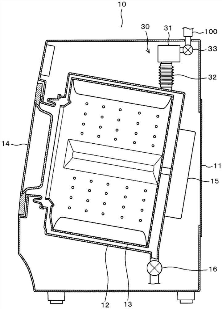
[0037] First, refer to Figure 1 to Figure 11 , an example in which the fine air bubble generator in the first embodiment is applied to a washing machine will be described. figure 1 The illustrated washing machine 10 includes an outer case 11 , a water tank 12 , a rotary tank 13 , a door 14 , a motor 15 , and a drain valve 16 . Additionally, the figure 1 The left side as the front side of the washing machine 10, the figure 1 The right side of is as the rear side of washing machine 10. In addition, let the installation surface side of the washing machine 10, that is, the vertical lower side be the lower side of the washing machine 10, and the opposite side of the installation surface, that is, the vertical upper side, be the upper side of the washing machine 10. The washing machine 10 is a so-called horizontal axis type front-loading washing machine in which the rotation axis of the rotation tank 13 is horizontal or descends downward.
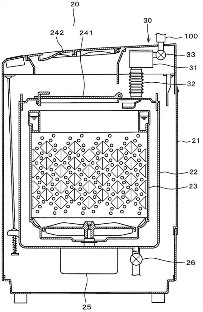
[0038] figure 2 The illustrated was...
no. 2 approach
[0099] Next, refer to Figure 12 to Figure 14 , and the second embodiment will be described.
[0100] In this second embodiment, the structure of the collision portion 60 , specifically, the number of protruding portions 61 is different from that of the above-mentioned first embodiment. In addition, "a" is appended to the code|symbol of the element whose concrete shape differs from the collision part 60 of 1st Embodiment.
[0101] The collision portion 60a of the second embodiment has three protrusions 61a. Furthermore, the division area 62a, the gap area 63a, and the slit area 64b are formed by these three protrusion parts 61a. Also in this embodiment, the width dimension Ws of the slit region 64a is set within a range of 0.35 mm to 0.50 mm. In addition, the length dimension Ls of the slit region 64b is set within a range of 0.60 mm to 0.70 mm. Furthermore, the value obtained by dividing the total area of the gap area 63 a and the slit area 64 a by the area of the ref...
no. 3 approach
[0106] Next, refer to Figure 15 to Figure 17 , and the third embodiment will be described.
[0107] In the third embodiment, the number of protrusions 61 is different from that of the first and second embodiments described above. In addition, "b" is appended to the code|symbol of the element whose concrete shape differs from the collision part 60 of 1st Embodiment.
[0108] The collision portion 60b of the third embodiment has five protrusions 61b. The division area 62b, the gap area 63b, and the slit area 64b are formed by these five protrusions 61b. Also in this embodiment, the width dimension Ws of the slit region 64b is set within a range of 0.35 mm to 0.50 mm. In addition, the length dimension Ls of the slit region 64b is set within a range of 0.60 mm to 0.70 mm. Furthermore, the value obtained by dividing the total area of the gap area 63 b and the slit area 64 b by the area of the reference area S is also set to be equal to or less than 0.5, specifically, withi...
PUM
| Property | Measurement | Unit |
|---|---|---|
| tensile yield strength | aaaaa | aaaaa |
Abstract
Description
Claims
Application Information