Supercharge Your Innovation With Domain-Expert AI Agents!

Pixel signal conversion method and device thereof

A technology of pixel signal and conversion method, applied in the field of pixel signal conversion method and device, can solve problems such as large viewing angle deviation defect and the like

Active Publication Date: 2019-01-08
HKC CORP LTD
View PDF4 Cites 12 Cited by
  • Summary
  • Abstract
  • Description
  • Claims
  • Application Information

AI Technical Summary

Problems solved by technology

[0006] Based on this, it is necessary to provide a solution for the problem of large viewing angle deviation when using R, G, and B three-color sub-pixel signals for driving on a color-mixing color display composed of W, R, G, and B four-color sub-pixels. A pixel signal conversion method and device

Method used


Image

  • Pixel signal conversion method and device thereof
  • Pixel signal conversion method and device thereof
  • Pixel signal conversion method and device thereof

Examples


Embodiment Construction

[0059] In order to make the purpose, technical solution and advantages of the present application clearer, the present application will be further described in detail below in conjunction with the accompanying drawings and embodiments. It should be understood that the specific embodiments described here are only used to explain the present application, and are not intended to limit the present application.

[0060] This application provides a pixel signal conversion method:

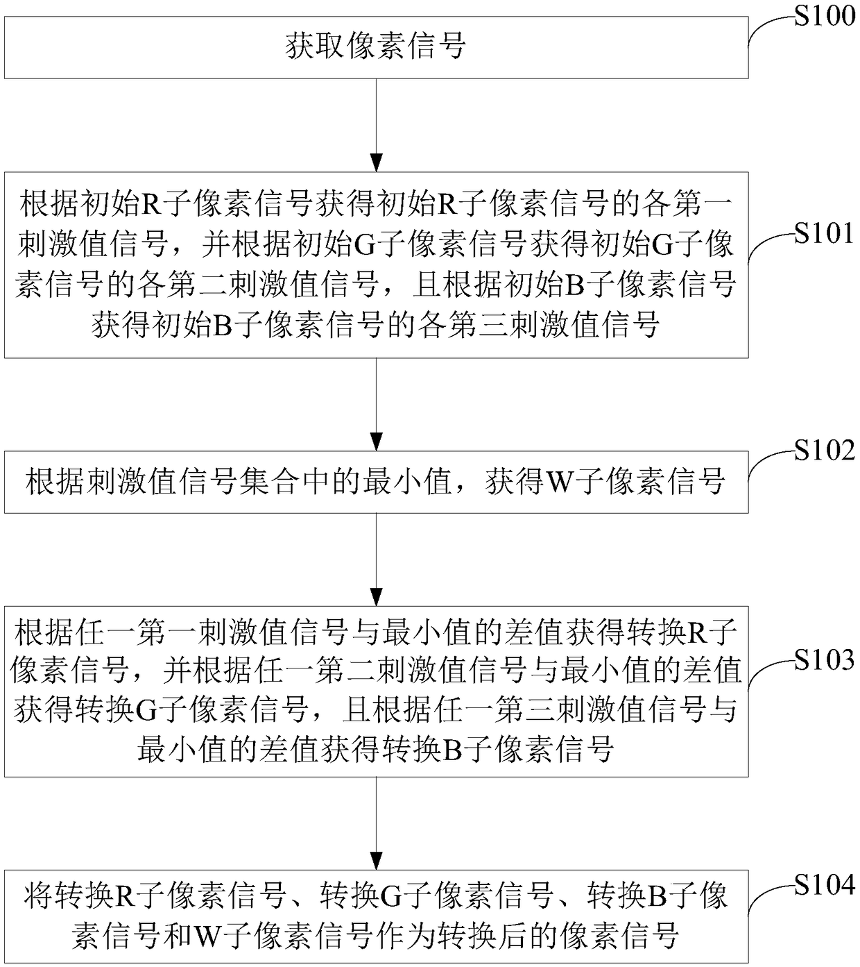
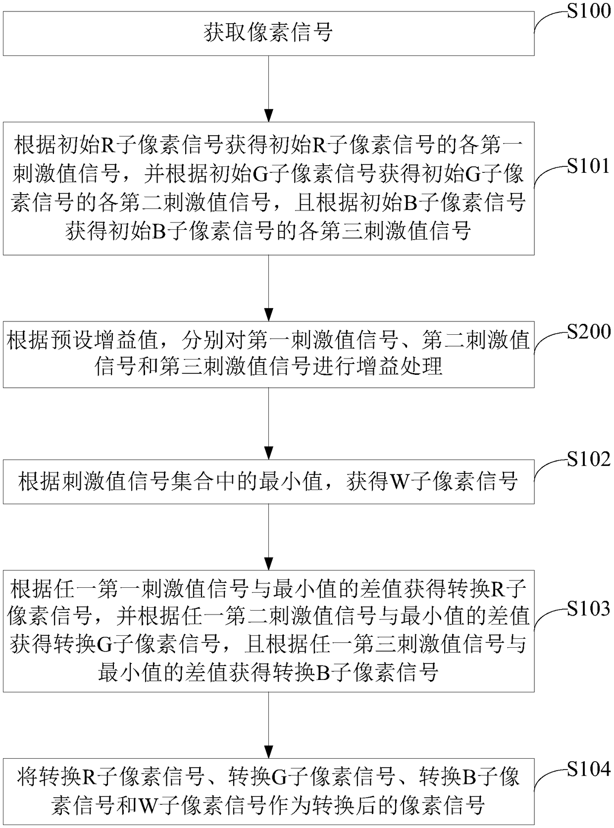
[0061] figure 1 It is a schematic flow chart of a pixel signal conversion method in an embodiment, such as figure 1 As shown, the pixel signal conversion method includes steps S100 to S104:

[0062] S100. Acquire pixel signals; the pixel signals include initial R sub-pixel signals, initial G sub-pixel signals, and initial B sub-pixel signals; wherein, the pixel signals are used to correspondingly drive R sub-pixels, G sub-pixels, and B sub-pixels in a specific pixel unit sub-pixel;

[0063] in, figu...


PUM


Abstract

The invention relates to a pixel signal conversion method and a device thereof. The method includes obtaining a first stimulus value signal, a second stimulus value signal, and a third stimulus valuesignal from an initial R sub-pixel signal, an initial G sub-pixel signal, and an initial B sub-pixel signal in a pixel signal. Further, a W sub-pixel signal is obtained by a minimum value in a stimulus value signal set consisting of a first stimulus value signal, a second stimulus value signal and a third stimulus value signal, and a converted R sub-pixel signal, a converted G sub-pixel signal anda converted B sub-pixel signal are sequentially obtained according to the minimum value. At last, convert R sub-pixel signal, convert G sub-pixel signal, convert B sub-pixel signal and W sub-pixel signal as converted pixel signal. Based on this, when the converted pixel signal is applied to the mixed color display composed of W, R, G, B sub-pixels, the display effect is closer to the actual performance of the original mixed color of R, G, B, which reduces the role bias defects of large vision and improves the display effect.

Description

technical field [0001] The present application relates to the field of liquid crystal display technology, in particular to a pixel signal conversion method and device. Background technique [0002] In a traditional liquid crystal display, the three-color light sources generated by the three sub-pixels of R (Red), G (Green), and B (Blue) are generally mixed to produce the desired display color. R, G, and B three-color light sources are absorbed by the photoresist material of the three sub-pixels of R, G, and B to absorb the light bands of the non-R, G, and B sub-pixel units, so that the three sub-pixels of R, G, and B produce corresponding R, G, B three-color light source. [0003] With the improvement of the resolution of the liquid crystal display, the increase of sub-pixels superimposes the decrease of the aperture ratio of the pixel corresponding to the sub-pixels, resulting in the loss of the transmittance of the high-resolution display and the decrease of the light eff...

Claims


Application Information

Patent Timeline
Patent Type & Authority Applications(China)
IPC IPC(8): G09G3/36
CPCG09G3/36G09G3/3607G09G2300/0452G09G2340/06G09G2360/16G09G3/2003
Inventor 康志聪
Owner HKC CORP LTD
Features
  • R&D
  • Intellectual Property
  • Life Sciences
  • Materials
  • Tech Scout
  • Unparalleled Data Quality
  • Higher Quality Content
  • 60% Fewer Hallucinations
Learn More