Field calibration method and system for composite measuring device

A measuring device and on-site calibration technology applied in the field of inertial navigation

Active Publication Date: 2019-01-11
HENGYANG ZHIGU TECH DEV CO LTD
View PDF4 Cites 6 Cited by
  • Summary
  • Abstract
  • Description
  • Claims
  • Application Information

AI Technical Summary

Problems solved by technology

[0003] Embodiments of the present invention provide an on-site calibration method and system for a...

Method used


Image

  • Field calibration method and system for composite measuring device
  • Field calibration method and system for composite measuring device
  • Field calibration method and system for composite measuring device

Examples


Embodiment Construction

[0035] The following will clearly and completely describe the technical solutions in the embodiments of the present invention with reference to the accompanying drawings in the embodiments of the present invention. Obviously, the described embodiments are some of the embodiments of the present invention, but not all of them. Based on the embodiments of the present invention, all other embodiments obtained by persons of ordinary skill in the art without creative efforts fall within the protection scope of the present invention.

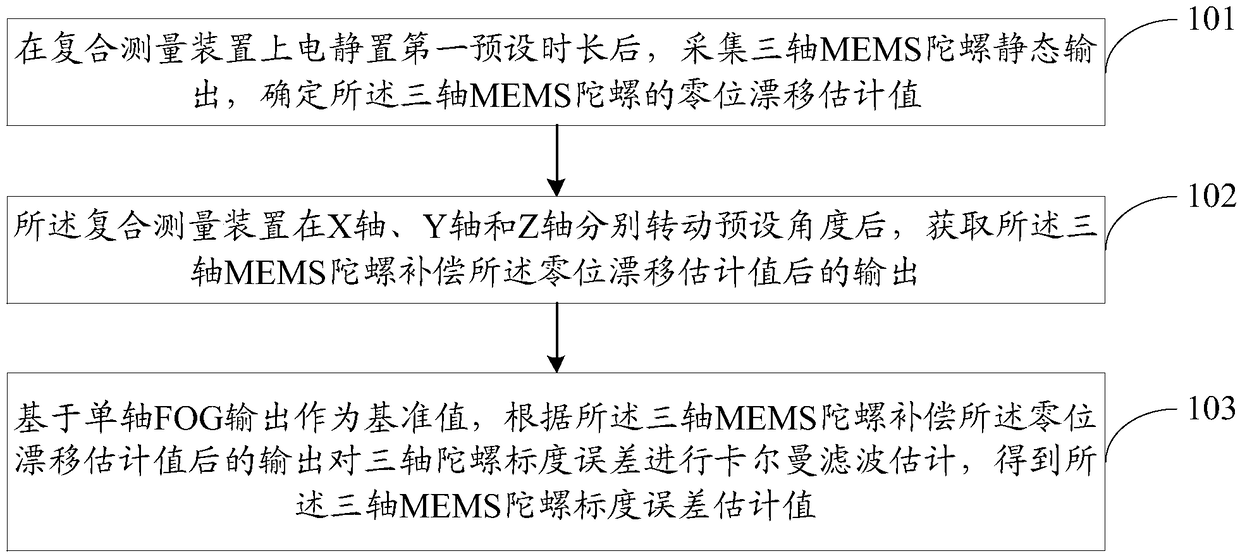
[0036] see figure 1 , figure 1 It is a flow chart of an on-site calibration method for a composite measuring device provided by an embodiment of the present invention, such as figure 1 shown, including the following steps:

[0037] Step 101, after the composite measurement device is powered on and left for a first preset period of time, collect the static output of the three-axis MEMS gyroscope, and determine the estimated value of the zero drift of ...


PUM


Abstract

The invention provides a field calibration method and system for a composite measuring device. The method comprises the following steps: performing electric standing on the composite measuring devicefor the first preset duration, acquiring static output of a triaxial MEMS (Micro-electromechanical Systems) gyroscope, and determining a zero drift estimated value of the triaxial MEMS gyroscope, wherein the zero drift estimated value is the mean of static output of the triaxial MEMS gyroscope in the second preset duration; respectively rotating the composite measuring device on an axis X, an axisY and an axis Z for preset angles, and acquiring output after the triaxial MEMS gyroscope compensates the zero drift estimated value; and by taking uniaxial FOG output as a reference value, performing Kalman filtering estimation on the triaxial gyroscope scale error according to the output after the triaxial MEMS gyroscope compensates the zero drift estimated value, thereby obtaining the triaxialMEMS gyroscope scale error estimated value. According to the method and system disclosed by the invention, field calibration of the composite measuring device is realized.

Description

technical field [0001] The invention relates to the technical field of inertial navigation, in particular to an on-site calibration method and system for a composite measuring device. Background technique [0002] The laboratory method of the three-axis MEMS (Micro-Electro-Mechanical System, micro-electro-mechanical system) gyroscope / uniaxial FOG gyroscope (Fiber Optical Gyroscope, fiber optic gyroscope) composite measurement device requires high-precision testing equipment and the calibration process is complicated. Taking the document "STPIM Calibration Method for Fiber Optic Gyroscope with Inclined Components" as an example, the prior art presents a calibration method for SINM with oblique gyroscope and accelerometer, using a high-precision turntable as the The benchmark belongs to the traditional discrete calibration method, mainly including dynamic angular rate calibration and static multi-position test. The calibration process is complex and relies on high-precision t...

Claims


Application Information

Patent Timeline
IPC IPC(8): G01C25/00
CPCG01C25/005
Inventor 张春熹王峥李彦冉龙俊
Owner HENGYANG ZHIGU TECH DEV CO LTD
Why Eureka
Try Eureka