Module, manufacturing method thereof, camera and electronic device

A module and circuit board technology, applied in the field of cameras, can solve the problems of tilting of the camera holder assembly, easy falling off of filters, layering and falling off, etc. Effect

Inactive Publication Date: 2019-01-15
GUANGDONG OPPO MOBILE TELECOMM CORP LTD
View PDF8 Cites 6 Cited by
  • Summary
  • Abstract
  • Description
  • Claims
  • Application Information

AI Technical Summary

Problems solved by technology

[0005] The embodiment of the present invention can solve the problem that the camera holder is easy to tilt and delaminate during the installation process, and can also solve the problem that the filter is easy to fall off or break under the impact of external force

Method used


Image

  • Module, manufacturing method thereof, camera and electronic device
  • Module, manufacturing method thereof, camera and electronic device
  • Module, manufacturing method thereof, camera and electronic device

Examples


Embodiment 1

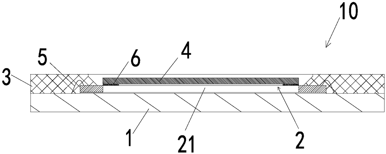
[0030] See figure 1 , which is Embodiment 1 of the present invention, provides a module 10 including a circuit board 1 , an image sensor 2 , a middleware 3 and an optical filter 4 .

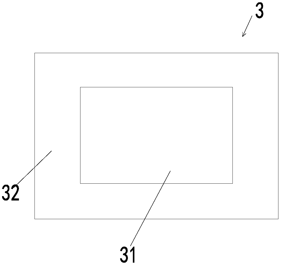
[0031] The image sensor 2 is fixed on the circuit board 1 and is electrically connected to the circuit board 1 through a connecting wire 5 . See figure 2 , the middle piece 3 has a hollow area 31 and an edge area 32, the edge area 32 of the middle piece 3 is fixed on the circuit board 1, the image sensor 2 has a photosensitive area 21, and the optical filter 4 is fixed on the image sensor by an adhesive 6 2 on the top surface of the photosensitive area 21, and the position of the optical filter 4 corresponds to the photosensitive area 21 of the image sensor 2, and the image sensor 2 and the optical filter 4 are embedded in the hollow area of ​​the middle piece 3.

[0032] In this embodiment, the optical filter 4 is made of blue glass, which can filter part of infrared rays and visible red ligh...

Embodiment 2

[0045] See Figure 5 , the main content of this embodiment is the same as that of Embodiment 1, the difference is that the image sensor 2 of this embodiment also has a non-photosensitive region 22, and the non-photosensitive region 22 is located at the outer periphery of the photosensitive region 21, and the optical filter 4 The edge area is bonded to the top surface of the non-photosensitive area 22 by means of an adhesive 6 . Since the optical filter 4 is connected to the non-photosensitive region 22 of the image sensor 2 , there is no limit to whether the light transmittance of the adhesive 6 is high or low.

[0046] Specifically, in order to make the connection between the middle piece 3 and the circuit board 1 stronger, the edge area of ​​the top surface of the circuit board 1 is fixed with a boss 11 , and the middle piece 3 wraps the boss 11 .

Embodiment 3

[0048] See Figure 6 The main content of this embodiment is the same as that of the first embodiment, except that the filter 4 of this embodiment is bonded to the top surface of the photosensitive region 21 of the image sensor 2 through an adhesive 6 with high light transmittance. Optionally, glue with a light transmittance higher than 92% can be used as the adhesive 6 . Since the adhesive 6 with high light transmittance is used, the optical filter 4 can be bonded to the image sensor 2 in a large area, and the connection between the optical filter 4 and the image sensor 2 is very firm. Also, the adhesive 6 does not interfere with entering the image sensor 2 .


PUM


Abstract

The invention is applicable to the technical field of a camera, and provides a lightweight and thin module and a manufacturing method thereof, a camera and an electronic device. The module comprises acircuit board, an image sensor, a middleware and an optical filter, wherein the optical filter is directly fixed on the top surface of the photosensitive area of the image sensor. The embodiment eliminates the base in the prior art and directly fixes the filter on the top surface of the photosensitive area of the image sensor, thereby saving components and reducing the filter attaching process, and avoiding the problem of tilting the base and the middleware in the installation process. As for that module design, since there is no base, the space of the module in the vertical direction is saveby 0.3 to 0.5 mm, so that the module is lighter and thin. In addition, since the image sensor itself is fixed on the circuit board, the image sensor can provide sufficient bearing strength to the filter, thereby improving the bearing capacity of the module when impacted by external forces, and making the filter not easy to fall off or break.

Description

technical field [0001] The invention belongs to the technical field of cameras, and in particular relates to a light and thin module, a manufacturing method thereof, a camera and an electronic device. Background technique [0002] The camera generally has basic functions such as video recording and static image capture. After the image is collected by the lens, the photosensitive component circuit and control component in the camera process the image and convert it into a digital signal that can be recognized by the computer. [0003] Cameras are used in various electronic devices. With continuous breakthroughs and innovations in technology, new cameras are emerging like mushrooms after rain. For example, it took more than ten years for the cameras used in mobile phones to go from the initial million to the current tens of millions, and the shooting quality has continuously entered a new level. [0004] From a structural point of view, the camera mainly includes: lens, moto...

Claims


Application Information

Patent Timeline
Patent Type & Authority Applications(China)
IPC IPC(8): H04N5/225
CPCH04N23/50H04N23/55H04N23/54
Inventor 张百成
Owner GUANGDONG OPPO MOBILE TELECOMM CORP LTD
Why Eureka
Try Eureka