Drill jig

A fixture and drilling machine technology, applied in clamping, manufacturing tools, boring/drilling, etc., can solve the problems of reducing workpiece quality, workpiece damage, time-consuming and labor-intensive, etc., and achieve improved drilling accuracy, scientific structure, and convenient use Effect

CN109420915AInactive Publication Date: 2019-03-05DEQING JINGYING INFORMATION TECH CO LTD
0 Cites 0 Cited by

Patent Information

Authority / Receiving Office
CN · China
Patent Type
Applications(China)
Current Assignee / Owner
Publication Date
2019-03-05
Estimated Expiration
Not applicable · inactive patent

Smart Images

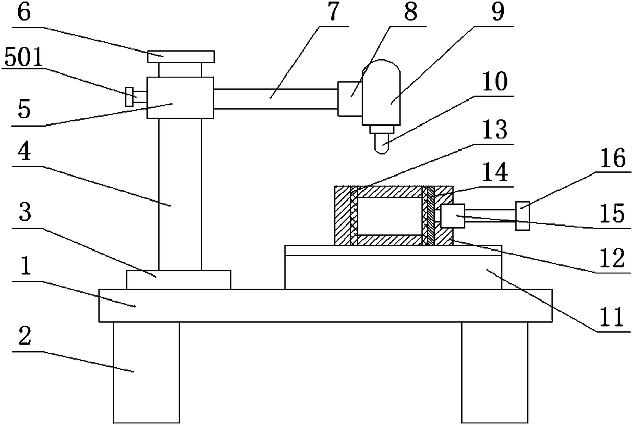
  • Figure 1
    Figure 1
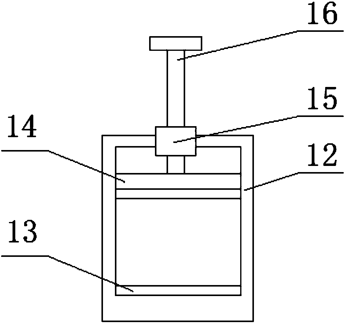
  • Figure 2
    Figure 2
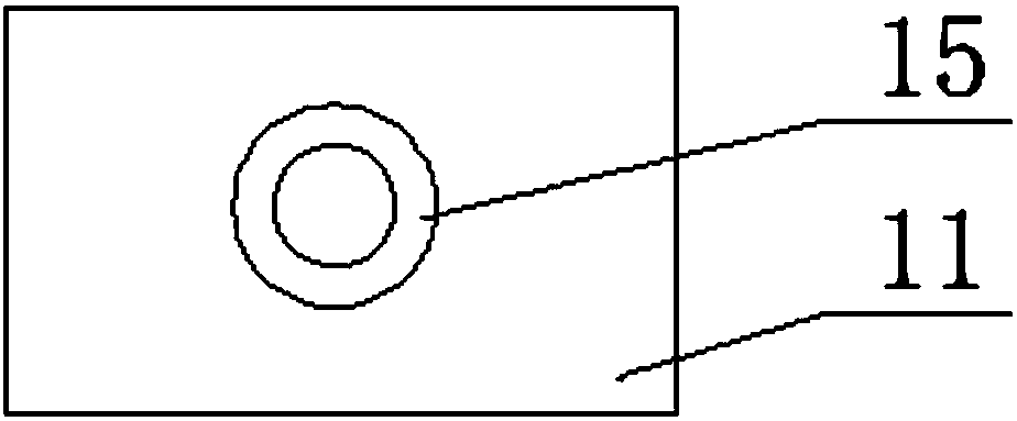
  • Figure 3
    Figure 3
Patent Text Reader

Abstract

The invention relates to the field of drills, in particular to a drill jig. The drill jig comprises a drill body, a support column, a drilling machine, a workbench and a jig frame; the upper end faceof the drill body is fixedly connected with a fixing base; a baffle is fixedly installed at the top end of the support column; a drilling machine frame is fixedly installed on the side end face of a sleeve; the drilling machine is fixedly arranged on the mounting face of a mounting base; the workbench is fixedly installed on the upper end face of the drill body; the inner end face of the clamp frame is in sliding connection with a movable clamping board; the outer end face of the movable clamping board is fixedly provided with a rubber board; a screw rod is arranged in the middle of the innerend face of the movable clamping board; through arrangement of the rubber board, the function of protecting clamped workpieces is achieved, and the clamped workpieces are prevented from being damaged;through fixed connection of the screw rod and the movable clamping board through a cylindrical pin, the adjusting performance of the movable clamping board is improved, the workpieces can be effectively clamped, and the drilling precision is improved; and the drill jig is scientific in structure, reasonable in design, convenient to use, safe, convenient to use, and high in practicability.
Need to check novelty before this filing date? Find Prior Art

Description

technical field

[0001] The invention relates to the technical field of drilling machines, in particular to a drilling machine fixture. Background technique

[0002] Drilling machine refers to a machine tool that mainly uses a drill bit to process holes on a workpiece. Usually, the rotation of the drill bit is the main movement, and the axial movement of the drill bit is the feed movement. The drilling machine has a simple structure and relatively low machining accuracy. It can drill through holes, blind holes, and replace special tools. , can be expanded, countersinked, reamed, or tapped. The characteristic of the drilling machine is that the workpiece is fixed, the tool rotates, and feeds along the direction of the spindle. The operation can be manual or motorized. Before processing, it must be The workpiece is clamped by the fixture, otherwise the quality of the processing will be reduced. With the development of the manufacturing industry, the application of drilling mach...

Examples

Embodiment Construction

[0019] The following will clearly and completely describe the technical solutions in the embodiments of the present invention with reference to the accompanying drawings in the embodiments of the present invention. Obviously, the described embodiments are only some, not all, embodiments of the present invention. Based on the embodiments of the present invention, all other embodiments obtained by persons of ordinary skill in the art without making creative efforts belong to the protection scope of the present invention.

[0020] see Figure 1-3 , the present invention provides a technical solution:

[0021] A drilling fixture, comprising a bed 1, a support column 4, a drilling machine 9, a workbench 11 and a fixture frame 12, the lower end surface of the bed 1 is fixedly mounted with a base 2, which has the function of supporting and fixing, the bed 1 The upper end surface of the upper end is fixedly connected with a fixed seat 3, and the support column 4 is fixedly installed ...