3D glass and film fitting fixture component

A technology for laminating fixtures and glass, applied in the direction of manufacturing tools, workpiece clamping devices, etc., can solve the problems that the fixtures cannot be used universally, the glass cannot be clamped very firmly, and the dimensional accuracy cannot be guaranteed.

Inactive Publication Date: 2019-03-12
湖南众从信息科技有限公司
View PDF0 Cites 0 Cited by
  • Summary
  • Abstract
  • Description
  • Claims
  • Application Information

AI Technical Summary

Problems solved by technology

[0002] The positioning method of the glass in the existing 3D bonding process is as follows: the front and rear of the glass in the groove are limited by a pair of clamping fixtures on the two short sides of the glass, and the glass upper cavity is turned 180° to the film of the lower cavity. For lamination, the clamping fixture and the four corners of the glass

Method used


Image

  • 3D glass and film fitting fixture component
  • 3D glass and film fitting fixture component
  • 3D glass and film fitting fixture component

Examples


Embodiment Construction

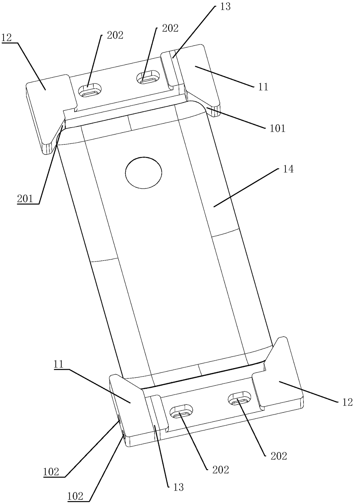
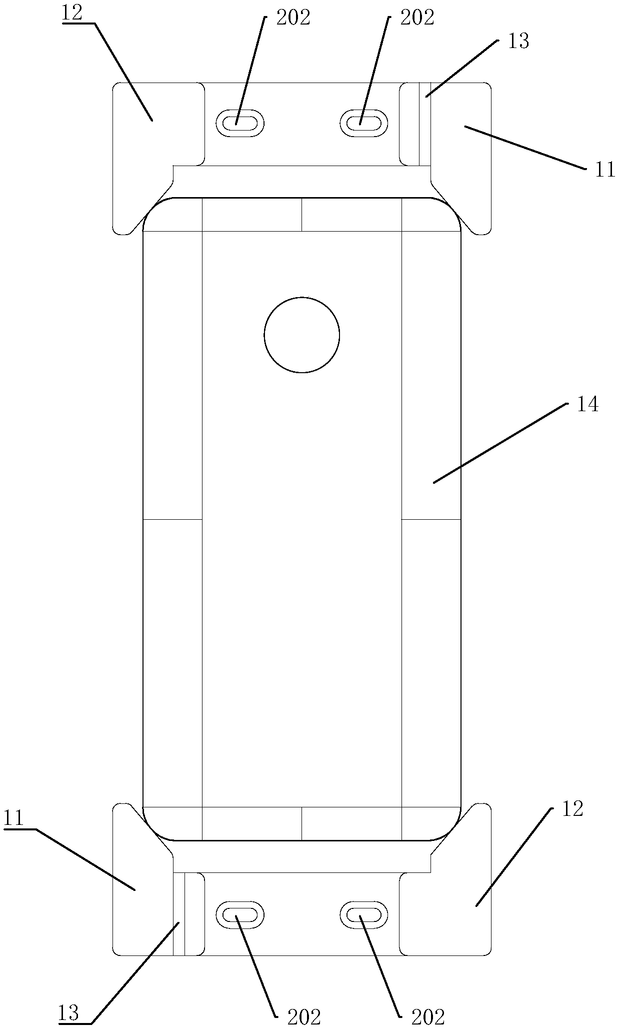
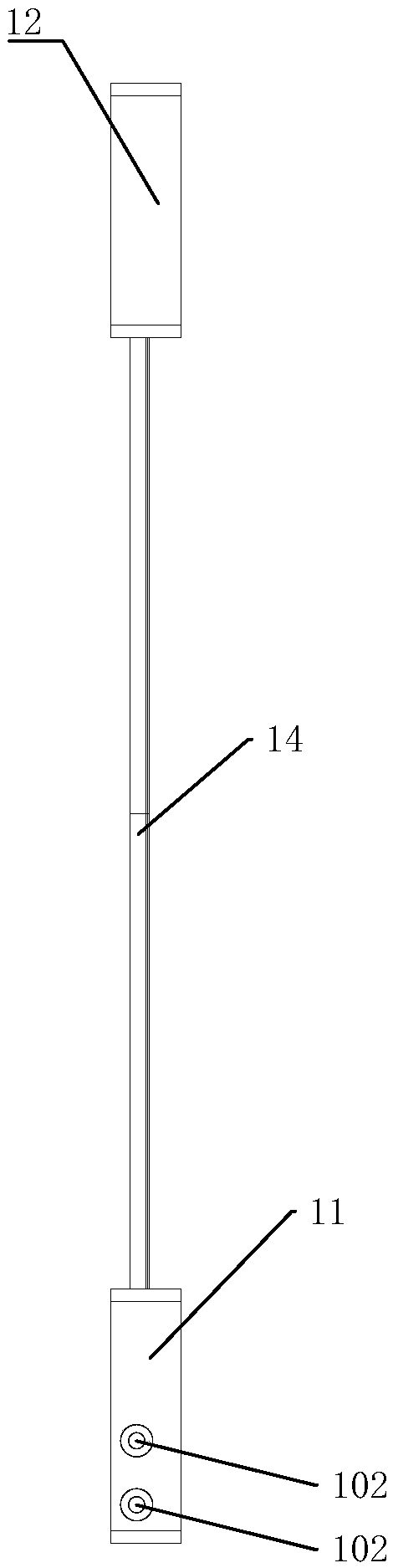
[0022] Such as Figure 1-Figure 5 Shown: a 3D glass film bonding fixture assembly of the present invention, used to clamp 3D glass 14, including a first clamping part 11, a second clamping part 12, and a spacer 13; the first clamping part 11 is provided with a clamping plane 101, the clamping plane 101 is in contact with a point on the corner of the 3D glass 14, the first clamping plane 101 is perpendicular to the upper and lower surfaces of the first clamping part 11, and the second clamping The part 12 is provided with a clamping plane 201 and a U-shaped screw hole 202, the clamping plane 201 is in contact with a point on the corner of the 3D glass 14, and the clamping plane 201 is perpendicular to the upper and lower surfaces of the first clamping part 11, The way of point contact enables the clamping part 11 and the clamping part 12 to better clamp the 3D glass 14 .

[0023] In this embodiment, the pad 13 is placed between the first clamping portion 11 and the second clam...


PUM


Abstract

The invention discloses a 3D glass and film fitting fixture component. The 3D glass and film fitting fixture component comprises first clamping portions, second clamping portions and pad blocks, wherein clamping planes of the first clamping portions and the second clamping portions make contact with one point of corners of 3D glass to clamp the glass, and it can be ensured that the fixture component is capable of being suitable for the 3D glass of different kinds through U-shaped bolt holes of the second clamping portions and the pad blocks of different thicknesses. By means of the 3D glass and film fitting fixture component, the problems in the prior art that clamping jigs cannot clamp the glass firmly and fixtures are not universal are solved.

Description

technical field [0001] The invention relates to the technical field of tooling, in particular to a 3D glass film bonding fixture. Background technique [0002] The positioning method of the glass in the existing 3D bonding process is as follows: the front and rear of the glass in the groove are limited by a pair of clamping fixtures on the two short sides of the glass, and the glass upper cavity is turned 180° to the film of the lower cavity. For lamination, the clamping fixture and the four corners of the glass are contacted by profiling. Since the glass and the fixture will produce certain errors during production, the clamping fixture cannot hold the glass firmly, and different 3D glasses need to be replaced. Different clamping fixtures lead to problems that the dimensional accuracy after lamination cannot be guaranteed and the fixtures cannot be used universally. Contents of the invention [0003] In order to solve the above-mentioned technical problems, the present i...

Claims


Application Information

Patent Timeline
IPC IPC(8): B25B11/00
CPCB25B11/00
Inventor 杨家明
Owner 湖南众从信息科技有限公司
Why Eureka
Try Eureka