Anastomosis device

an anastomosis device and anastomosis tube technology, applied in the field of anastomosis devices, can solve the problems of subsequent stricture, patients are often plagued by the long-term complication of stricture, and narrowing of the lumen, so as to reduce the risk of long-term contracture, prevent stricture, and narrow the lumen

Inactive Publication Date: 2011-01-20
NEW YORK UNIV
View PDF20 Cites 1414 Cited by
  • Summary
  • Abstract
  • Description
  • Claims
  • Application Information

AI Technical Summary

Benefits of technology

[0014]The anastomosis surgical staplers of the present invention are similar to existing end to end anastomotic staplers, commonly called “EEA staplers,” such as those shown in U.S. Pat. No. 4,646,745 to Noiles, which is hereby incorporated by reference in its entirety. However, the head portion differs greatly from other EEA anastomosis stapling devices, because the present invention employs varying mating edges and staple lines, resulting in a w-plasty style anastomosis (i.e., an anastomosis in which the edges of a wound are trimmed in the shape of a W and closed in a zigzag fashion). In this way, narrowing of the lumen and subsequent stricture is avoided, which is a significant advantage over prior EEA devices and anastomosis methods. A typical application of the surgical stapler of the present invention is connecting together two sections of the hollow tubular body organ (e.g., two intestinal sections) by means of an array of staples, which surrounds a lumen or passageway between the interiors of the connected organ sections.
[0015]Surgically, W-plasties are commonly used for reconstructive purposes, to

Problems solved by technology

A common problem in anastomosis procedures is that such procedures are limited to straight line incisions, which heal in a constricted fashion.
The resultant circular or ring-like scar may lead to narrowing of the lumen and subsequent stricture.

Method used


Image

  • Anastomosis device
  • Anastomosis device
  • Anastomosis device

Examples


first embodiment

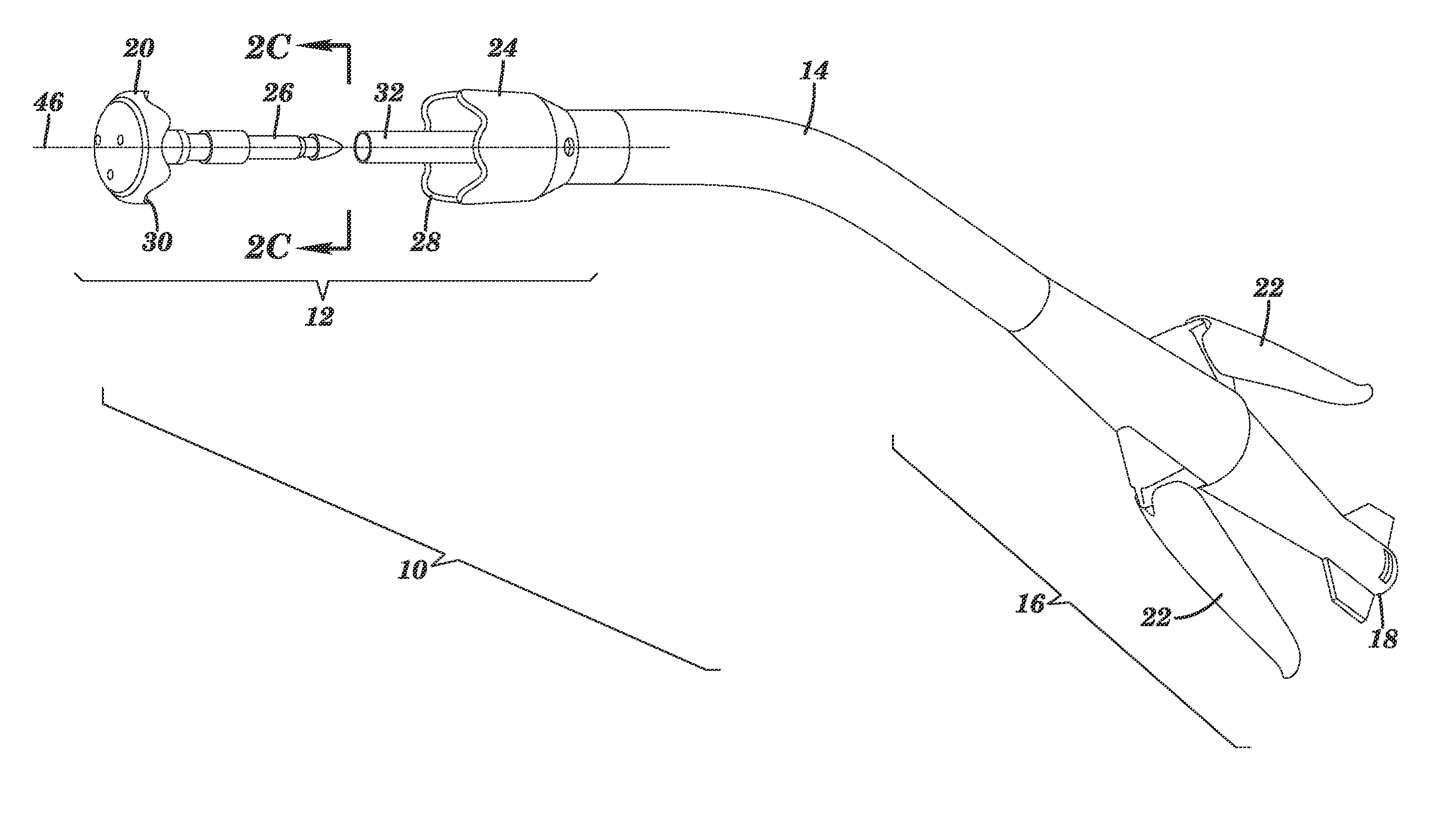
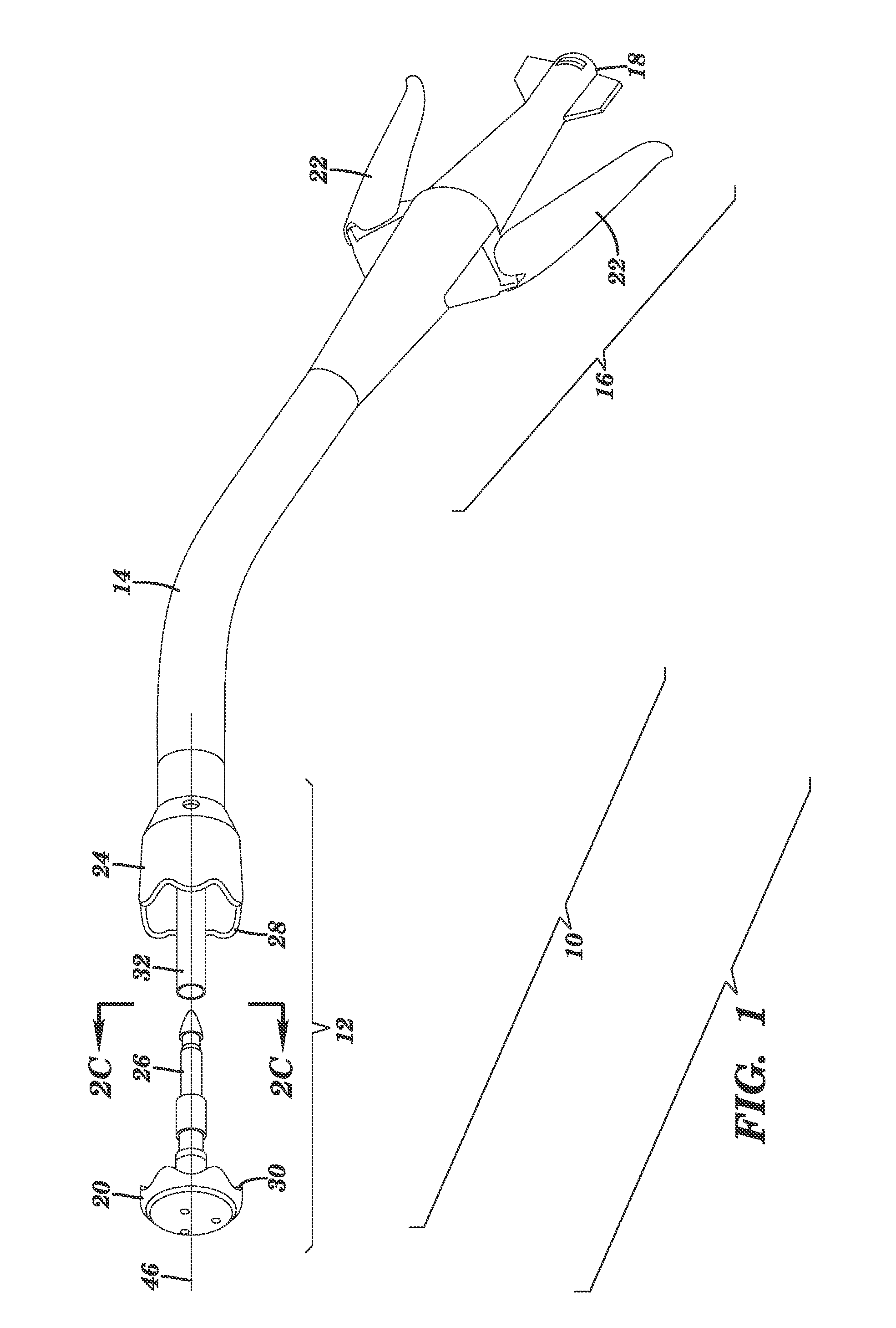
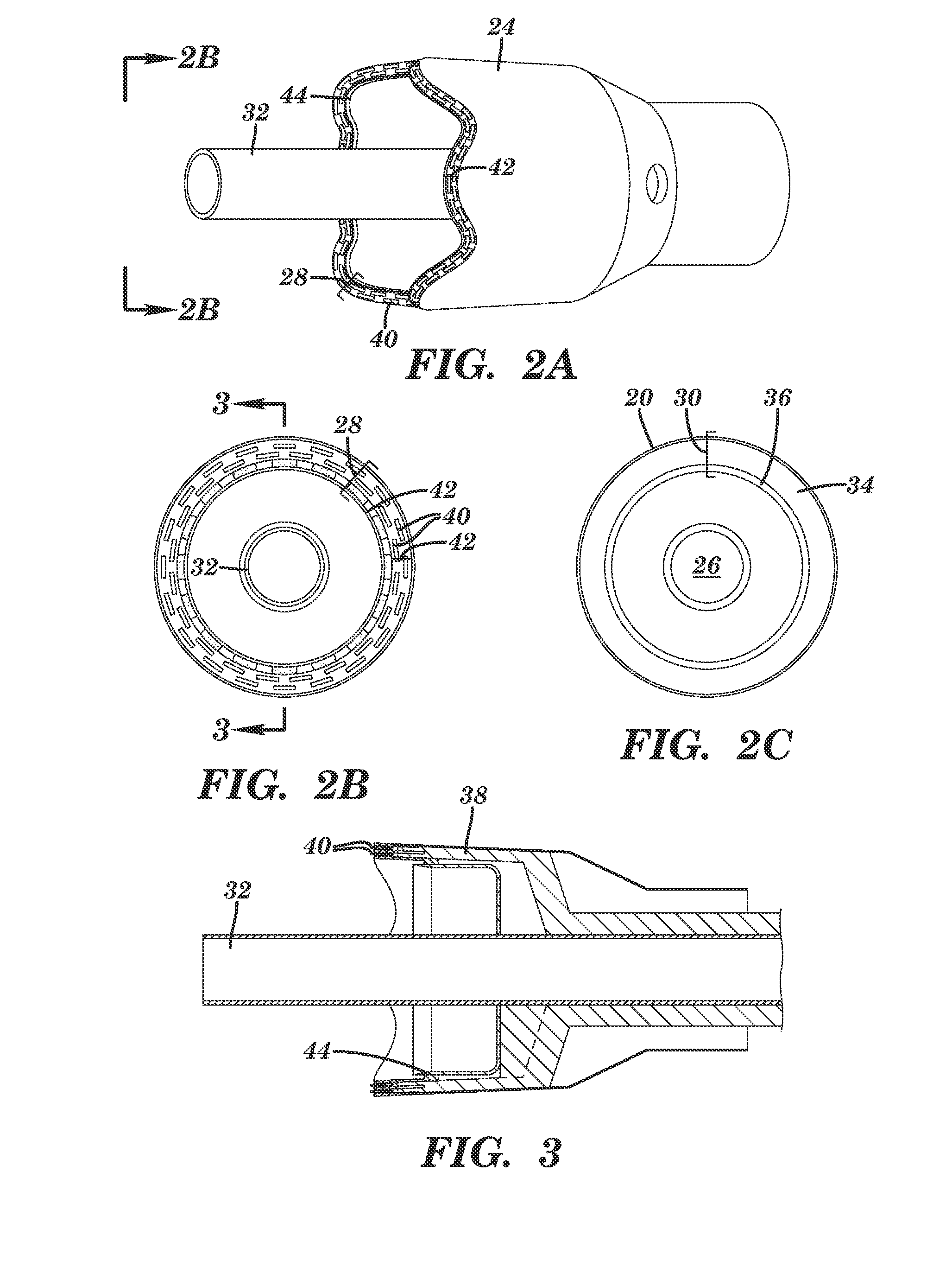
[0029]Actuating head portion 12, is best described with reference to FIGS. 1, 2A-C, and 3. Referring to FIG. 1, actuating head portion 12 includes anvil assembly 20, mounted to the end of stem portion 26, and associated stapling portion 24. Stapling portion 24 includes stapling portion mating edge 28 and anvil portion 20 includes anvil portion mating edge 30. Stapling portion 24 also includes stem receiving device 32, which matingly engages with stem portion 26 of anvil 20 upon operation of anastomosis surgical stapler 10, as described infra. Tubular body 14 is mounted for longitudinal reciprocal motion relative to stapling portion 24 so that the spacing between opposing faces of anvil assembly 20 and stapling portion 24 may be varied. As can be seen in FIG. 2C, anvil assembly 20 includes staple anvil 34 and knife anvil or cutting ring 36.

[0030]Referring now to FIG. 3, stapling portion 24 includes staple cartridge or housing 38, which initially holds a plurality of surgical staples...

second embodiment

[0032]Anastomosis surgical stapler 110, according to the present invention, is described with reference to FIGS. 4, 5A-B, and 6. Referring now to FIG. 4, actuating head portion 112 includes anvil assembly 120 mounted to the end of stem portion 126 and associated staple portion 124. Stapling portion 124 includes a stapling portion mating edge 128 and anvil portion 120 includes an anvil portion mating edge 130. Stapling portion 124 also includes stem receiving means 132, which matingly engages with stem portion 126 of anvil 120 upon operation of anastomosis surgical stapler 110, as described below. Tubular body 114 is mounted for longitudinal reciprocal motion relative to stapling portion 124 so that the spacing between opposing faces of anvil assembly 120 and stapling portion 124 can be varied. As can be seen in FIG. 5C, anvil assembly 120 includes staple anvil 134 and knife anvil or cutting ring 136.

[0033]Referring now to FIG. 6, stapling portion 124 includes a staple cartridge or h...


PUM

PropertyMeasurementUnit
Waveaaaaaaaaaa
Distanceaaaaaaaaaa

Abstract

The present invention is directed to a circular anastomosis surgical stapler and methods of use. The circular anastomosis surgical stapler includes an operator control assembly, a tubular shaft having a distal end that is associated with a head portion, and an actuating head portion. The actuating head portion includes a detachable anvil portion with an axially extending stem portion. The anvil portion is engagable with the remainder of the head portion, which receives an array of staples. The head portion also includes an associated stapling portion with a stapling mechanism for firing an array of staples against the anvil portion. The anvil portion and the head portion matingly engage along a mating edge. The mating edge is defined by locations around the stem portion spaced from a particular position on the axis of the stem portion at axially and/or radially varying distances.

Description

[0001]This application claims the benefit of U.S. Provisional Patent Application Ser. No. 61 / 225,990, filed Jul. 16, 2009, which is hereby incorporated by reference in its entirety.FIELD OF THE INVENTION[0002]The present invention relates to an anastomosis device.BACKGROUND OF THE INVENTION[0003]Various types of surgical fastener applying instruments are known for the application of surgical fasteners to tissue. A common type of surgical fastener is a surgical staple. Surgical stapling instruments typically have a mechanism for firing a plurality of staples from a staple holding cartridge and an anvil positioned opposite the staple cartridge against which the staples are formed. Such instruments include, for example, linear staplers, which typically apply one or more parallel rows of staples, and circular staplers, which typically apply one or more concentric / circular rows of staples. In use, the surgeon will place tissue between the staple cartridge and anvil and, by firing the ins...

Claims


Application Information

Patent Timeline
IPC IPC(8): A61B17/115
CPCA61B17/115A61B2017/111A61B2017/07257
Inventor LEVINE, JAMIE P.
Owner NEW YORK UNIV
Why Eureka
Try Eureka