Image display apparatus

An image display device and image technology, applied in image communication, optical observation device, transportation and packaging, etc., can solve problems such as difficult to intuitively grasp

Inactive Publication Date: 2019-03-15
TOYOTA JIDOSHA KK
View PDF7 Cites 0 Cited by
  • Summary
  • Abstract
  • Description
  • Claims
  • Application Information

AI Technical Summary

Problems solved by technology

If such a composite image is displayed, it is difficult for the occupant to intuitively grasp the sense of distance between the object (for example, another vehicle) appearing in the composite image and the own vehicle on which the occupant is boarded from the composite imag

Method used


Image

  • Image display apparatus
  • Image display apparatus
  • Image display apparatus

Examples


Embodiment Construction

[0018] Hereinafter, embodiments of an image display device will be described with reference to the drawings. Hereinafter, a description will be given using the vehicle 1 of the embodiment in which the image display device is mounted.

[0019] (1) Configuration of vehicle 1

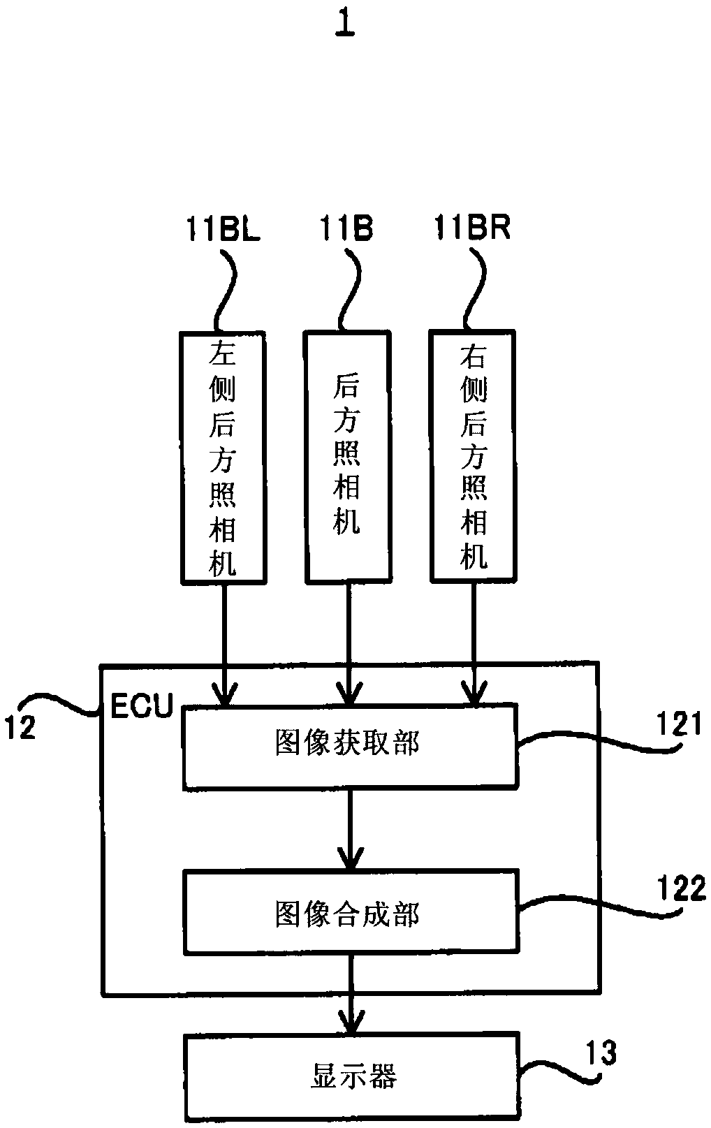
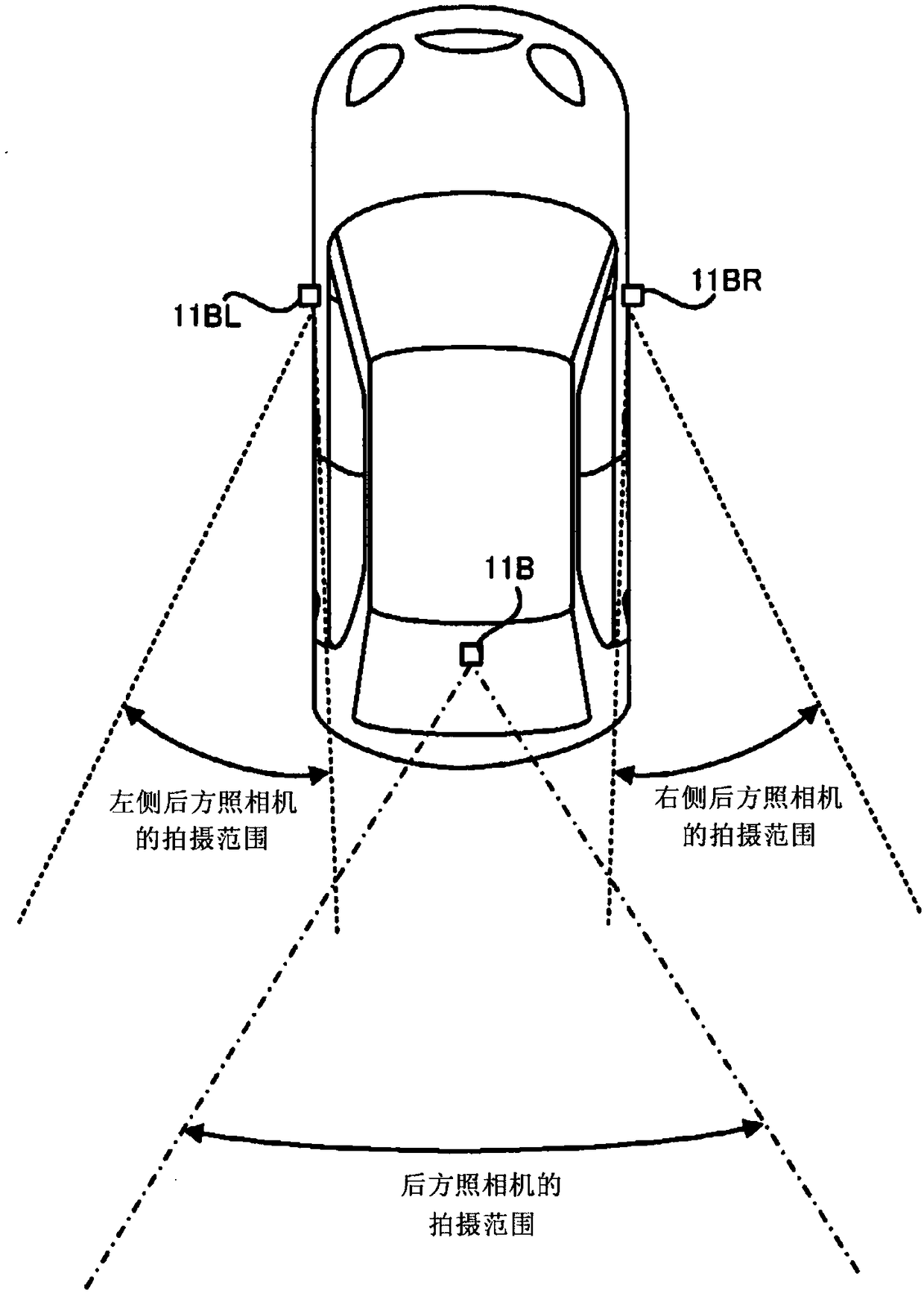
[0020] First, refer to figure 1 as well as figure 2 The configuration of the vehicle 1 according to the present embodiment will be described. figure 1 It is a block diagram showing the configuration of the vehicle 1 according to the present embodiment. figure 2 It is a plan view showing the installation positions and imaging ranges of the rear camera 11B, the left rear camera 11BL, and the right rear camera 11BR in the vehicle 1 of the present embodiment. In addition, in the description below, right, left, and rear refer to the right, left, and rear, respectively, with respect to the traveling direction of the vehicle 1 unless otherwise noted.

[0021] Such as figure 1 As shown, the vehicle 1 is eq...


PUM


Abstract

The present invention provides an image display apparatus that synthesizes images captured by a plurality of imaging units mounted on a vehicle to generate a synthesized image, and can generate a synthesized image of the sense of a distance between an object and a vehicle that are easily grasped by the occupant in the composite image. An image display apparatus has: a first imaging device (11B) for imaging an area on the rear of a vehicle (1); a second imaging device (11BL, 11BR) for imaging an area on the rear and side of the vehicle; a synthesizing device (12) for generating a synthesized image in which a first image captured by the first imaging device and a second image captured by the second imaging device are adjacent to each other and a vanishing point of the first image in the synthesized image is different from a vanishing point of the second image in the synthesized image; and a displaying device (13) for displaying the synthesized image.

Description

technical field [0001] The present invention relates to the technical field of an image display device that synthesizes images captured by a plurality of cameras mounted on a vehicle and can display the synthesized images. Background technique [0002] An example of such an image display device is described in Patent Document 1. Specifically, Patent Document 1 describes an image display device in which a left image captured by a left camera whose imaging center is located on the left side from the rear of the vehicle, and a left image captured by a right camera whose imaging center is located on the right side from the rear of the vehicle are described in Patent Document 1. The right image and the rear image captured by the rear camera whose imaging center is directly behind the vehicle are synthesized, and the synthesized image can be displayed. [0003] In addition, Patent Document 2 can be cited as a prior art document related to the invention of the present application....

Claims


Application Information

Patent Timeline
IPC IPC(8): H04N7/18H04N5/262
CPCH04N5/262H04N7/181B60R2300/605B60R1/00B60R2300/303B60R2300/306B60R2300/8046B60R2300/8066H04N5/2624H04N5/2628H04N21/47H04N21/4316H04N23/698H04N23/90H04N7/18B60R2300/105
Inventor 浅井五朗
Owner TOYOTA JIDOSHA KK
Why Eureka
Try Eureka