
Integration tower capable of eliminating white smoke plume and various contaminants
A technology for white smoke and pollutants, which can be used in combination devices, gas treatment, membrane technology, etc., to solve the problems of inefficient removal of sub-micron particles and mist droplets, low site requirements, and low cost, and to save on mist removal. The effect of flushing water, small footprint and low cost
- Summary
- Abstract
- Description
- Claims
- Application Information
AI Technical Summary
Problems solved by technology
Method used
Image

Examples
Embodiment Construction
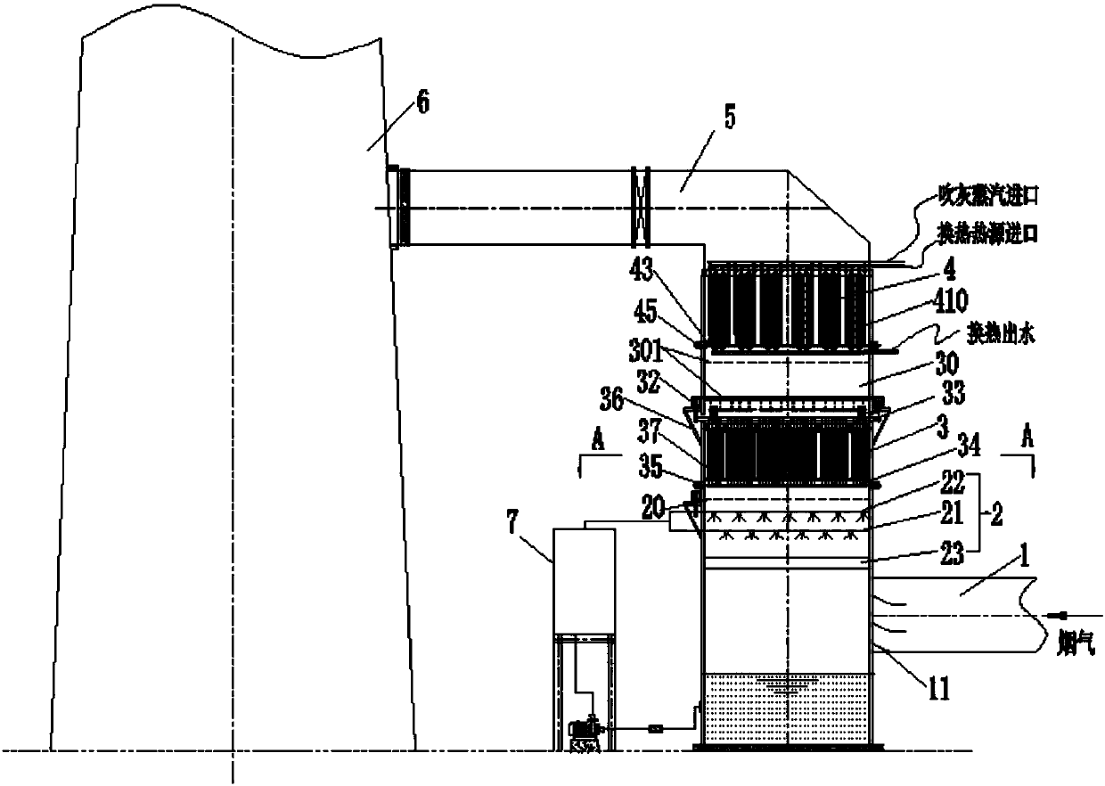
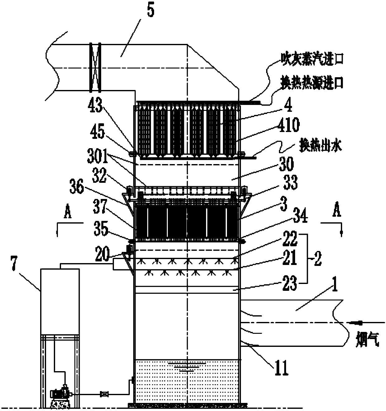
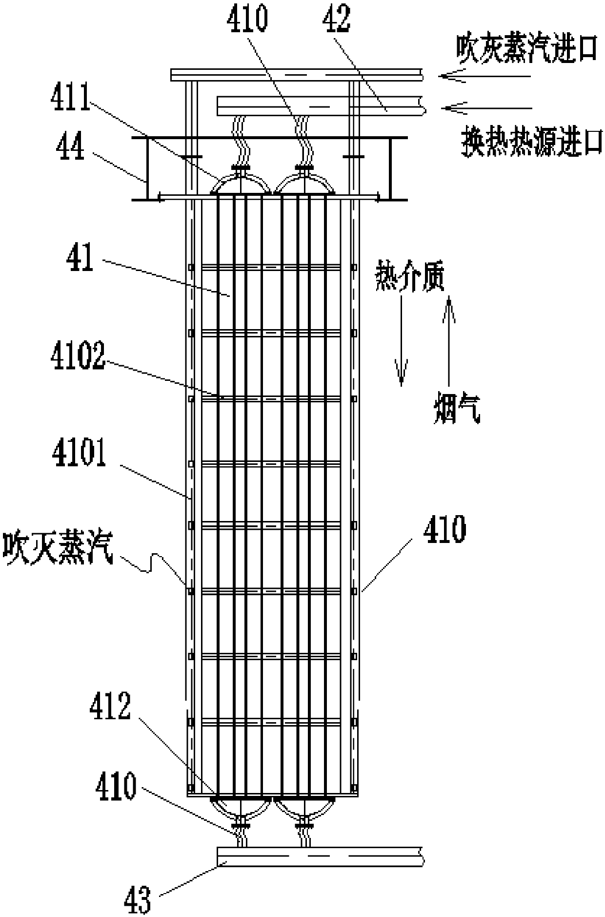
[0036] refer to Figure 1 to Figure 6 The present invention is an integrated tower capable of removing white smoke plumes and various pollutants, including a tower body, a power supply part and an external circulating water system, and is characterized in that: the tower body includes five areas distributed from bottom to top, It includes flue gas inlet area 1, spray cooling and charging area 2, wet electrostatic precipitator area 3, tubular flue gas reheating area 4, and flue gas outlet area 5. The outlet end of the flue gas inlet area 1 is connected to the spray The cooling and charging area 2 is connected. The spray cooling and charging area 2 is provided with a spray cooling layer 21 and a water mist charging layer 22. The spray cooling layer 21 is used to cool the flue gas. The water The mist charging layer 22 is used to inductively charge the particles and mist; the wet electrostatic precipitator area 3 is provided with a hexagonal dust collecting plate 31 and an externa...
PUM
 Abstract
Description
Claims
Application Information