Electric connector

A technology of electrical connectors and connecting parts, which is applied in the direction of connections, circuits, and parts of connecting devices, which can solve problems affecting high-frequency characteristics, signal distortion, and unequal lengths, and achieve the effect of ensuring high-frequency characteristics

Inactive Publication Date: 2019-03-29
DEYI PRECISION ELECTRONIC IND CO LTD PANYU
View PDF4 Cites 3 Cited by
  • Summary
  • Abstract
  • Description
  • Claims
  • Application Information

AI Technical Summary

Problems solved by technology

Since the insulating body is designed sideways, the conductive terminals are also designed to be arranged in a runway line, so that the front ends of the conductive terminals are located on the same vertical plane and contact the electronic card, and the solder feet of the conductive terminals are located on the same horizontal plane and connected to the electronic card. On the circuit board, the length of the conductive terminals decreases sequentially from the outside to the inside, but this causes the lengths of the two differential signal terminals of the same pair to be unequal, and the shorter differential signal terminal is relatively longer than the longer differential signal terminal. Under normal circumstances, the signal can be transmitted to the electronic card or circuit board faster, and the asynchronous transmission of the signal will easily lead to signal distortion, which will eventually affect the high-frequency characteristics

Method used


Image

  • Electric connector
  • Electric connector
  • Electric connector

Examples


Embodiment Construction

[0036] In order to facilitate a better understanding of the purpose, structure, features, and effects of the present invention, the present invention will now be further described with reference to the drawings and specific embodiments.

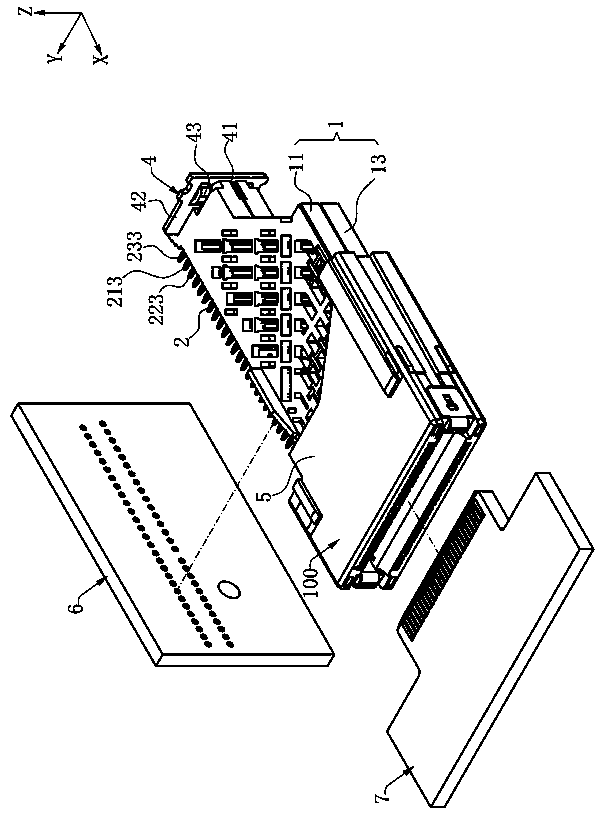
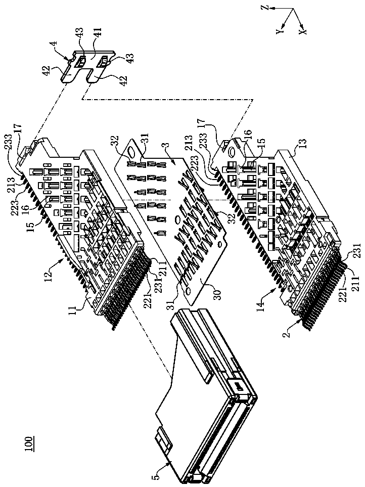
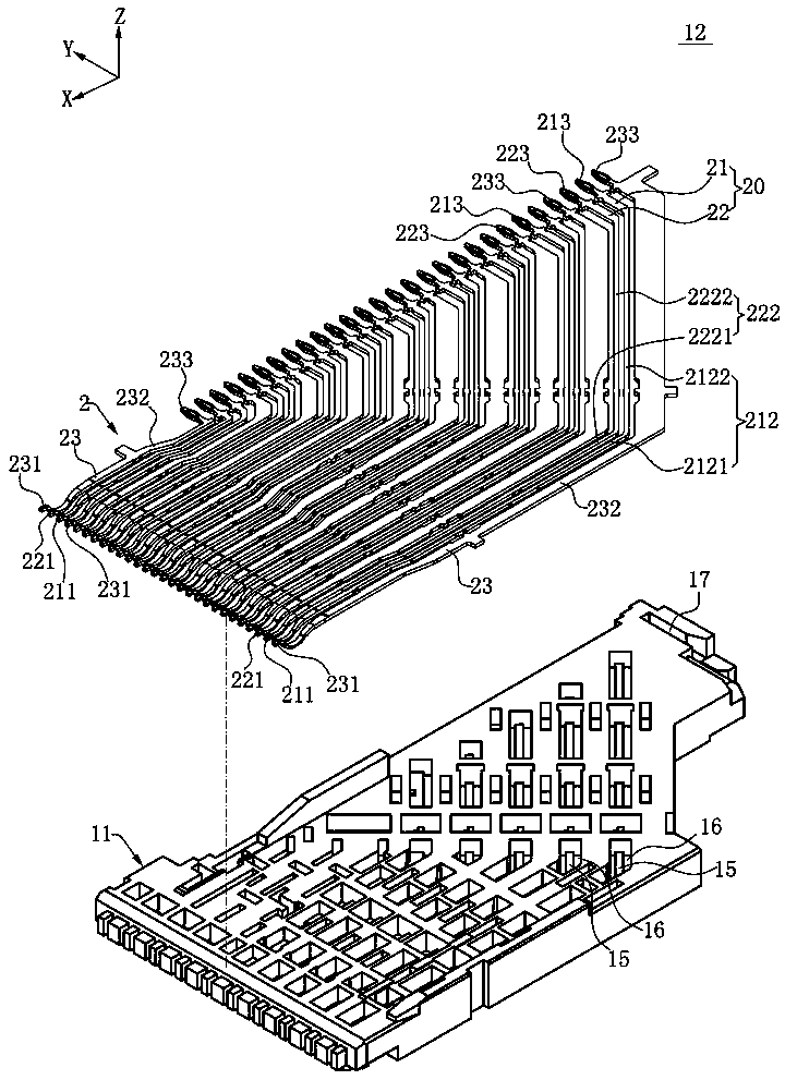
[0037] Such as figure 1 , figure 2 with image 3 As shown, the electrical connector 100 of the present invention defines a front-to-back direction X, a left-to-right direction Y, and an up-down direction Z that are perpendicular to each other, and the rightward and backward directions are the outward directions, and the leftward and forward directions The direction is the inward direction. The electrical connector 100 includes an insulating body 1, two upper and lower rows of conductive terminals 2, a shielding sheet 3, a positioning member 4, and a housing 5. Each row of the conductive terminals 2 is further divided into groups of differential signal pairs 20 and Multiple ground terminals 23. The electrical connector 100 is used to electrical...


PUM


Abstract

The invention discloses an electric connector which is used for electrically connecting a first butt joint component to a second butt joint component. The electric connector comprises an insulating body; at least one differential signal pair which is disposed on the insulating body, and comprises a long signal terminal and a short signal terminal, wherein the length of the long signal terminal isgreater than the length of the short signal terminal, the thickness of the long signal terminal is greater than the thickness of the short signal terminal, and the long signal terminal has a first contact portion, a first guiding portion and a first bend portion which is connected with the first contact portion and the first guiding portion, the short signal terminal has a second contact portion,a second guiding portion, and a second bent portion which is connected with the second contact portion and the second guiding portion. The first contact portion and the second contact portion simultaneously make contact with the first butt joint component, and the first guiding portion and the second guiding portion simultaneously make contact with the second butt joint member.

Description

Technical field [0001] The invention relates to an electrical connector, in particular to an electrical connector for transmitting high-frequency signals. Background technique [0002] With the development of science and technology today, there are more and more types of electrical connectors, and more and more application fields. Therefore, the requirements for electrical connectors are getting higher and higher, including high-frequency signal transmission and miniaturization of electrical connectors. Design and other aspects. Because of this, in a certain environment, the electrical connector needs to be designed as a side vertical type to adapt to a special environment. [0003] There is a side vertical electrical connector for electrically connecting an electronic card to a circuit board. The side vertical electrical connector includes an insulating body and a plurality of conductive terminals housed in the insulating body. The conductive terminals further include a plurality...

Claims


Application Information

Patent Timeline
Patent Type & Authority Applications(China)
IPC IPC(8): H01R13/405H01R13/502H01R13/627H01R13/629H01R13/6461H01R13/652
CPCH01R13/405H01R13/502H01R13/627H01R13/629H01R13/6461H01R13/652H01R12/735H01R13/514H01R13/516H01R13/6467H01R13/6471H01R13/6474H01R13/6476H01R13/6587H01R13/2442H01R13/26H01R13/646H01R2107/00
Inventor 隆权
Owner DEYI PRECISION ELECTRONIC IND CO LTD PANYU
Why Eureka
Try Eureka