Electronic paramagnetic imager

An electronic paramagnetic and imager technology, applied in medical science, sensors, diagnostic recording/measurement, etc., can solve problems such as long measurement time and poor effect of low-concentration samples, and achieve short data collection time, high-power input, The effect of a large measuring range

Active Publication Date: 2019-04-16
常州特征信息科技有限公司
View PDF10 Cites 1 Cited by
  • Summary
  • Abstract
  • Description
  • Claims
  • Application Information

AI Technical Summary

Problems solved by technology

Traditional measurement uses continuous wave method, which is not effective for low-concentration samples and takes a long time to measure

Method used


Image

  • Electronic paramagnetic imager
  • Electronic paramagnetic imager
  • Electronic paramagnetic imager

Examples


specific Embodiment 1

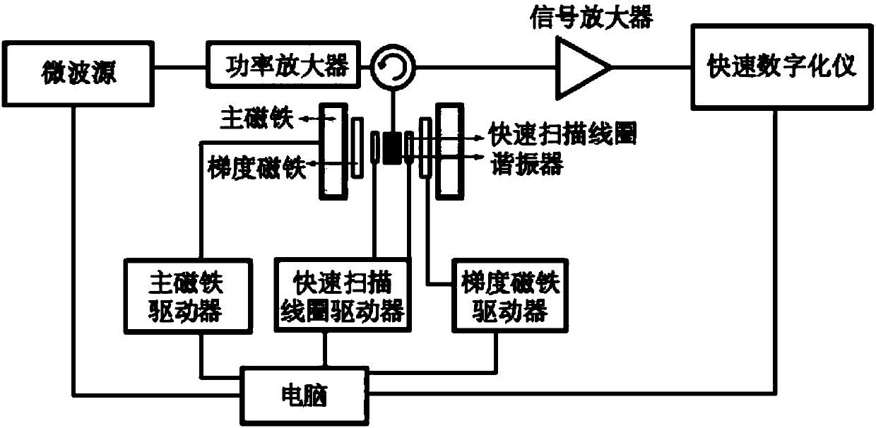
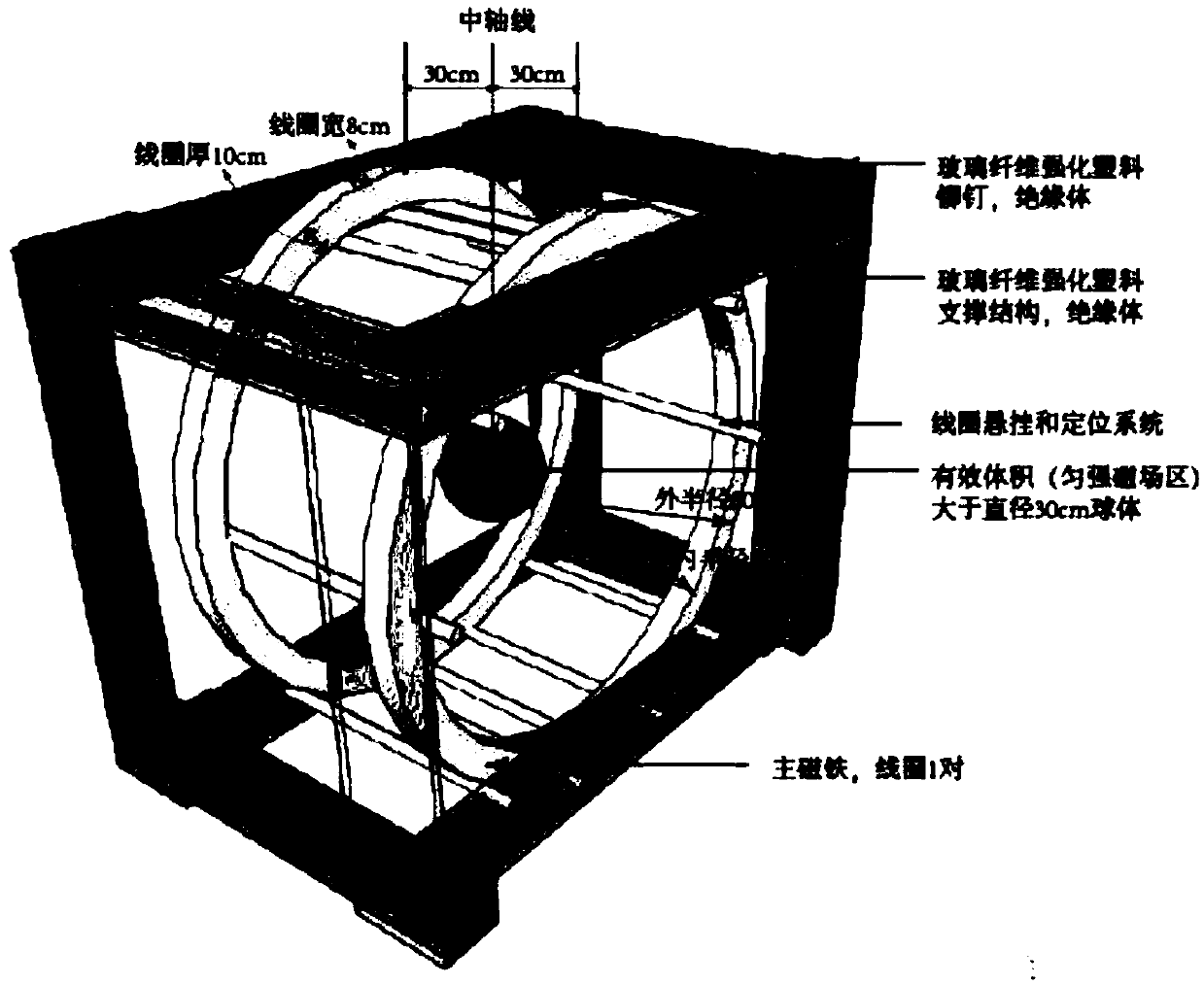
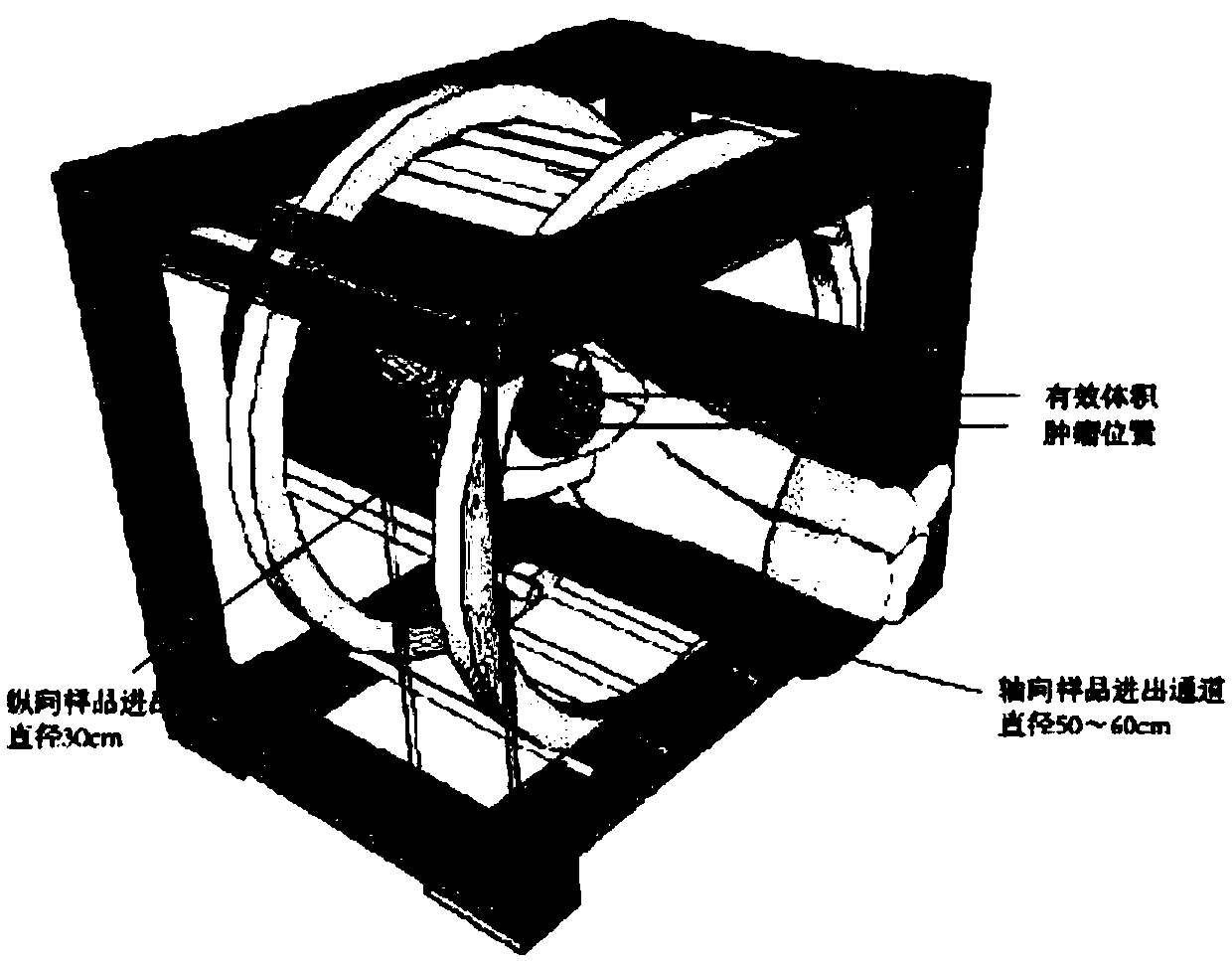
[0023] according to figure 1 with figure 2 Shown: An electron paramagnetic imager comprising a sample container, a fast-scan resonator, a pair of fast-scan coils, a pair of main magnets, a pair of gradient magnets, a main magnet driver, a gradient magnet driver, a fast-scan coil driver, a microwave sources, power amplifiers, signal amplifiers, fast digitizers and computers;

[0024] One end of the main magnet driver is connected to the main magnet, one end of the gradient magnet driver is connected to the gradient magnet, one end of the fast scanning coil driver is connected to the fast scanning coil, the fast scanning resonator is connected to the sample container, the sample container is connected to the power amplifier and one end of the signal amplifier at the same time, and the other end of the power amplifier is One end is connected to the microwave source, the other end of the signal amplifier is connected to the fast digitizer, the main magnet driver, the gradient ma...


PUM


Abstract

The invention discloses an electronic paramagnetic imager. The electronic paramagnetic imager comprises a sample container, a quick-scanning resonator, a pair of quick-scanning coils, a pair of main magnets, a pair of gradient magnets, a main magnet driver, a gradient magnet driver, a quick-scanning coil driver, a microwave source, a power amplifier, a signal amplifier, a quick digitalizerand a computer. A signal is directly recorded by the quick digitalizer, and the electronic paramagnetic imager has the advantages that the ratio of signal to noise is extremely high, the data collecting timeis short, and big-power input is achieved, and the frequency can be adjusted. Theelectronic paramagnetic imager reconstructs a two-dimensional image of a tumor according to space distribution of a sample signal. The work frequency of the imager is low frequency about 250 MHz, the electronic paramagnetic imager can measure a tumor model of a mouse and the human body, the microwave permeability is better, the measuring range is larger relatively, and an operation does not need to be performed.

Description

technical field [0001] The invention relates to the technical field of electron paramagnetic imaging, and relates to an electron paramagnetic imaging instrument. Background technique [0002] Electron Paramagnetic Resonance (EPR) is a very powerful science and technology for studying the electronic structure of free radicals and metals. The theoretical basis of this technology comes from the famous "Zeman effect" in physics, that is, the energy level of electrons is split in a magnetic field. Electron paramagnetic resonance was first observed in 1944 by former Soviet scientist Zavorsky. [0003] At present, domestic institutions capable of performing electron paramagnetic resonance measurements are only found in scientific research institutes of universities, and have not yet been popularized to other industries such as medical institutions. At present, all the instruments for electronic paramagnetic experiments are imported, and can only perform high-frequency measurement...

Claims


Application Information

Patent Timeline
Patent Type & Authority Applications(China)
IPC IPC(8): A61B5/05
CPCA61B5/0507
Inventor 施怡琳陈奥夏赵美淇
Owner 常州特征信息科技有限公司
Why Eureka
Try Eureka